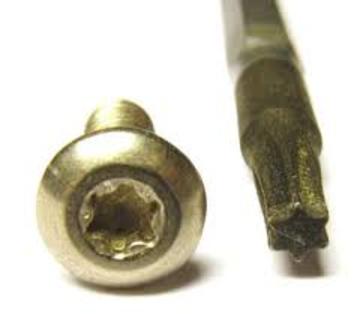
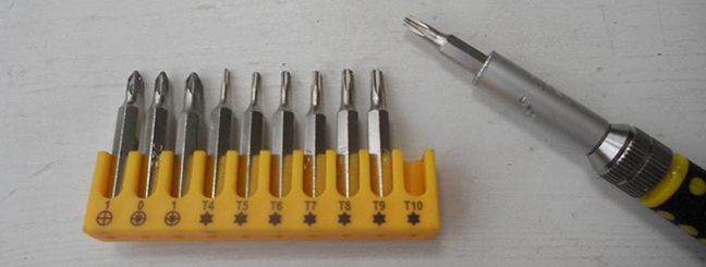
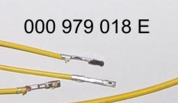
You will need:
ATTENTION!!! When installing a color MFD, there are 3 most important points.
|
|||||||||||||||||||||||||||||||||||||||||||||||||||||||||||||||||||||||||||||||||||||||||||||||||||||||||||||||||||||||||||||||||||||||||||||||||||||||||||||||||||||||||||||||||||||||||||||||||||||||||||||||||||||||||||||||||||||||||||||||||||||||||||||||||||||||||||||||||||||||||||||||||||||||||||||


|
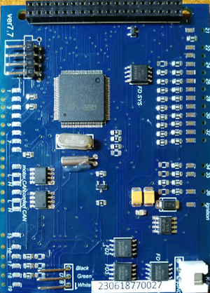
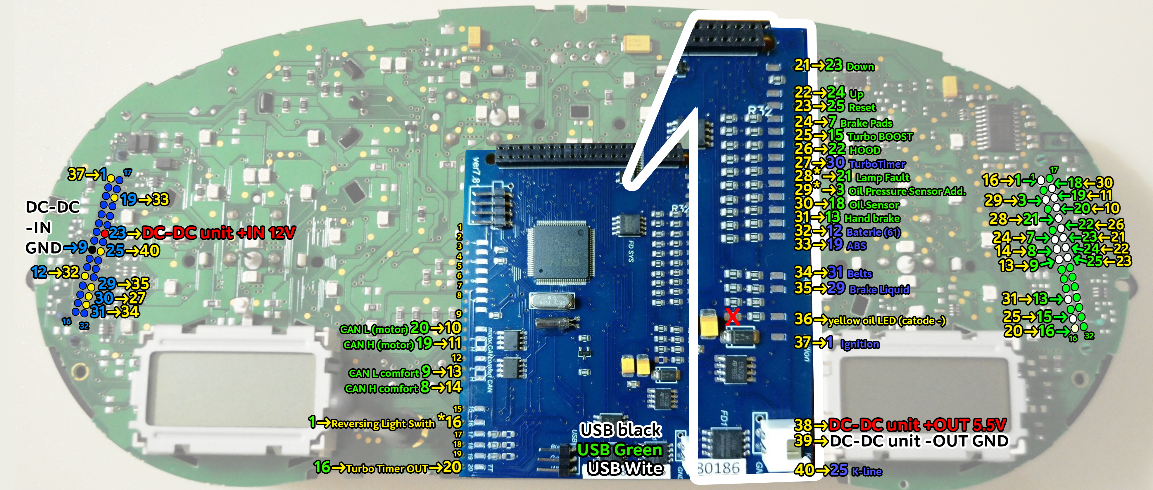
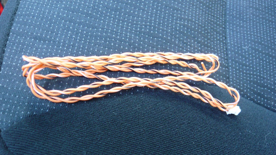
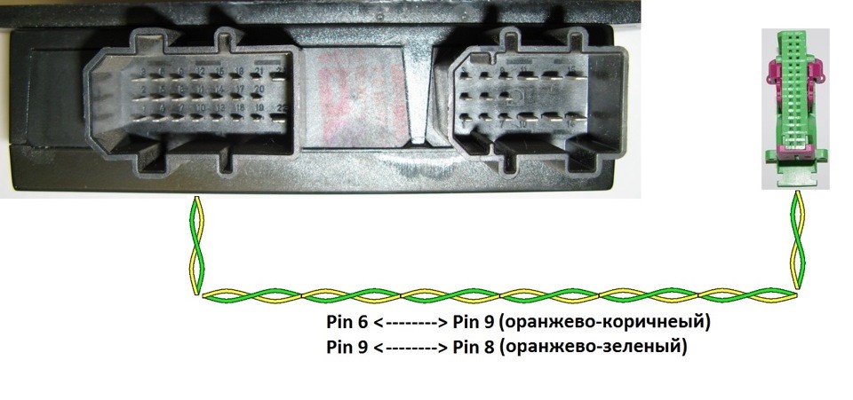
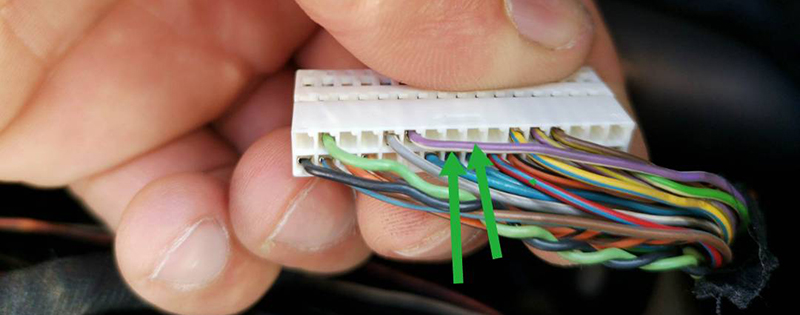
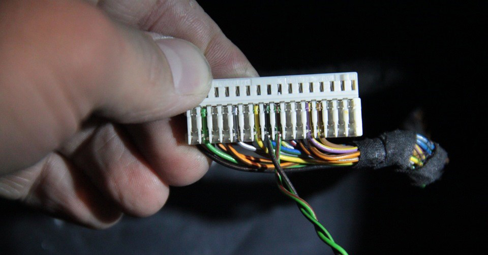
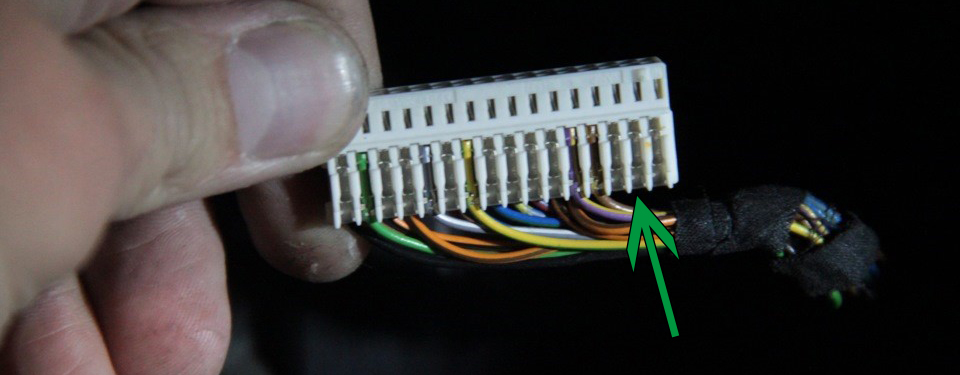
2.4 Be sure to twist in a spiral the wires, which you will be connecting to CAN bus.
Comfort CAN bus — 8 and 9 pins of Green connector;
|
 |
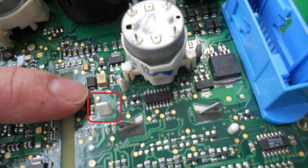
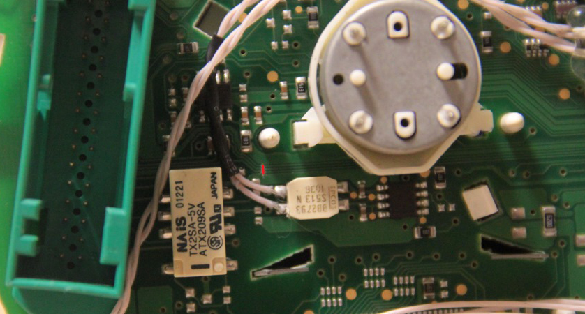
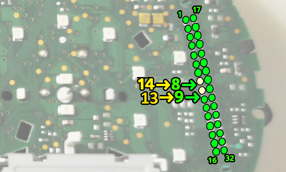
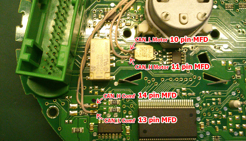
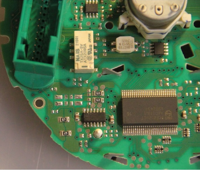
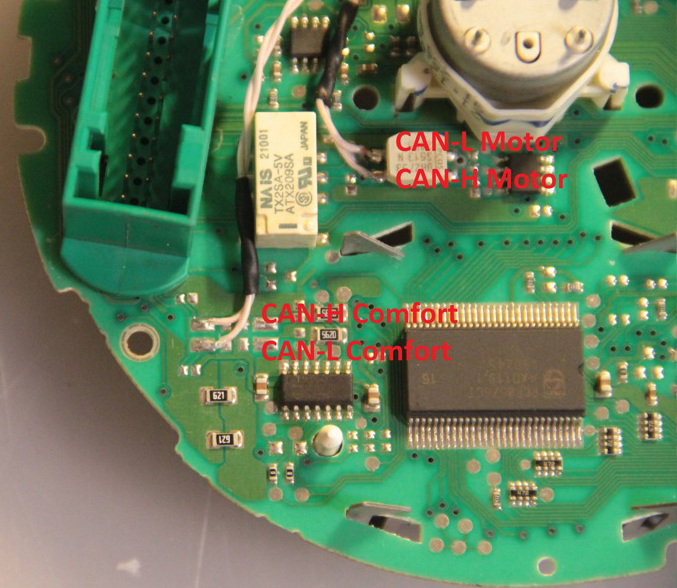
There are 2 ways to connect CAN bus wires. Choose what is convenient for you.
| 1-st way: solder the wires to to the pins of the green connector | 2-nd way: solder the wires to the points, indicated in the photo | ||
 |
 |
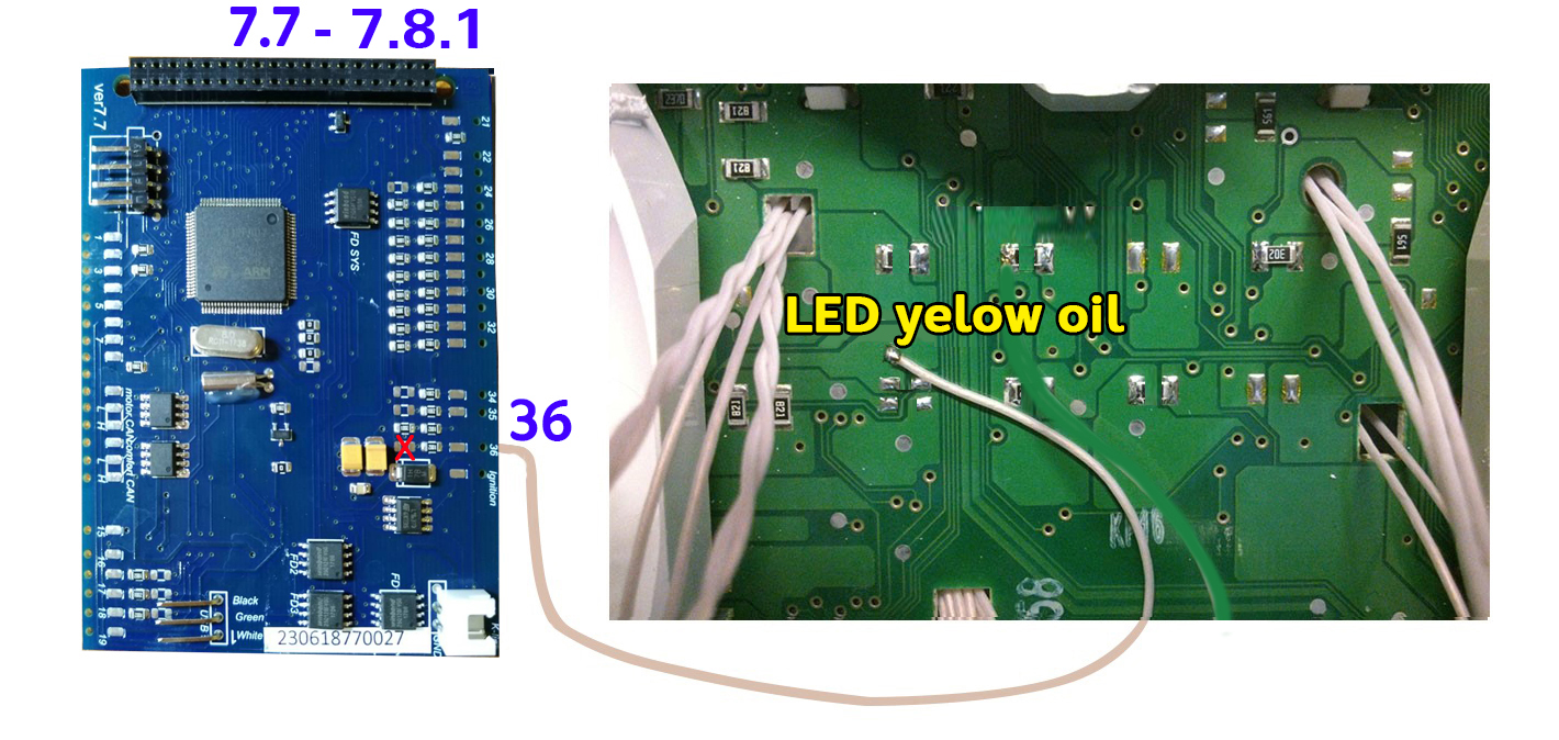
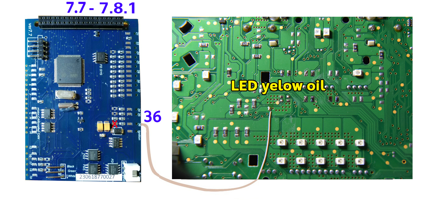
2.5
Important!
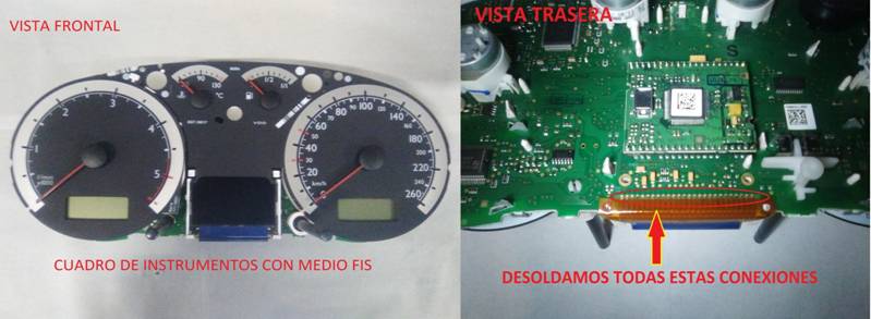
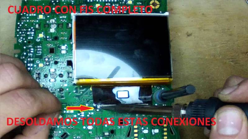
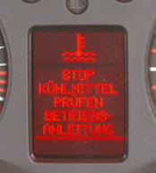
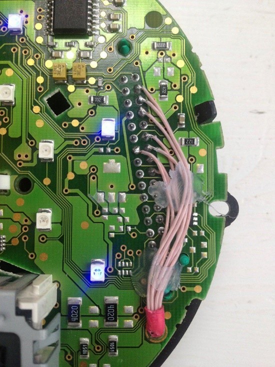
If you have noFIS or halfFIS dashboard,
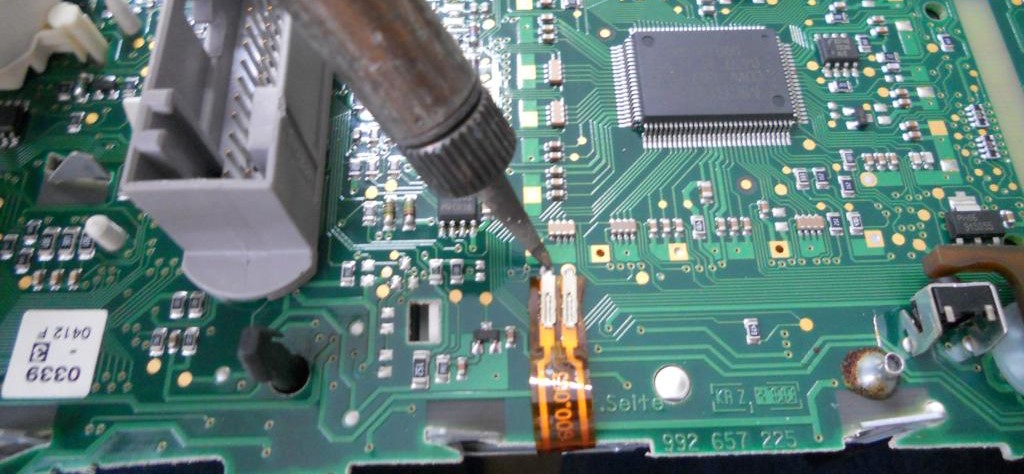
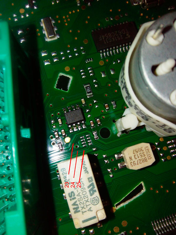
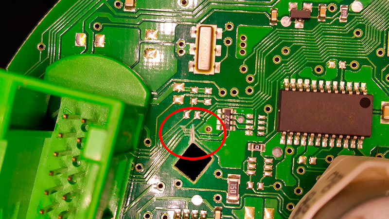
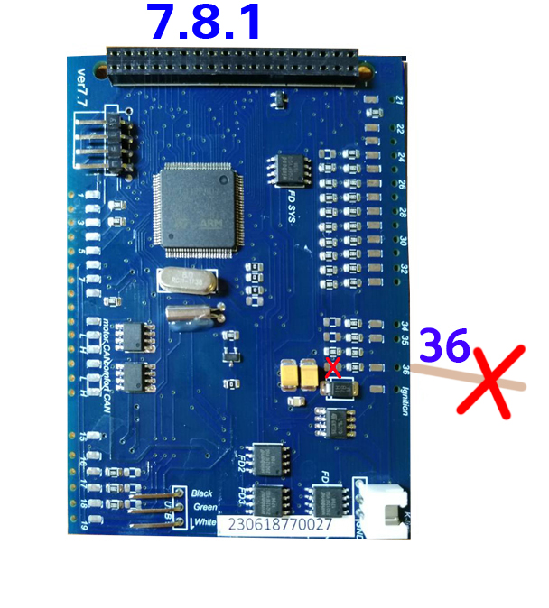
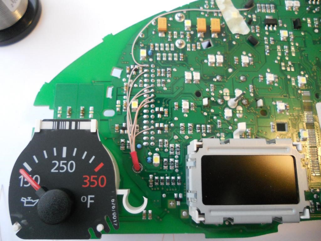
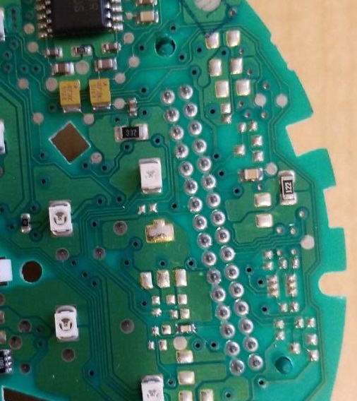
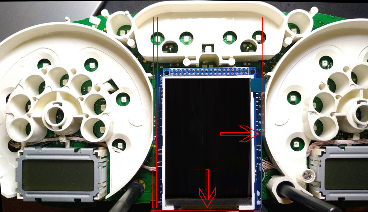
you need to solder the wire from 36 pin of MFD board to the
LED`s cathod, on the dashboard.
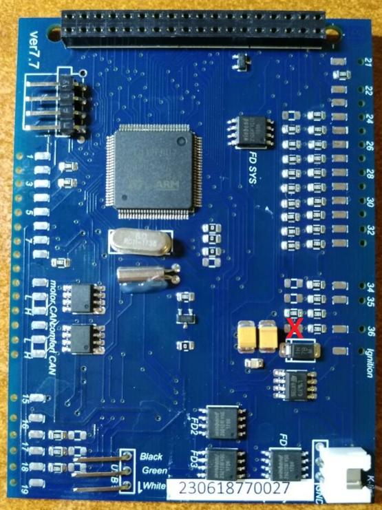
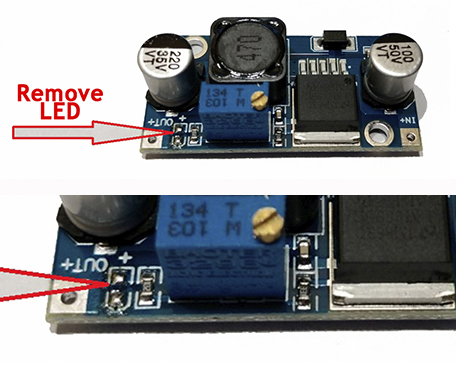
And
you need to remove 3kOhm (302 or 3001) resistor from 36 pin of MFD
board.
|
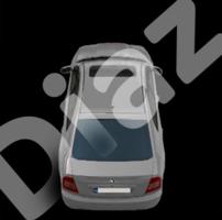
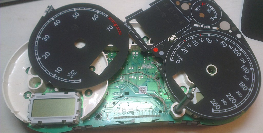
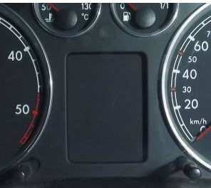
Панель приборов без БК (noFIS) выглядит вот так:
|
 |
|
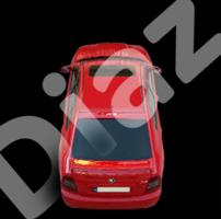
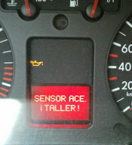
Панель приборов с
Половинкой БК (halfFIS)
выглядит вот так:
|
|
|
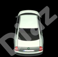
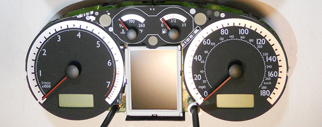
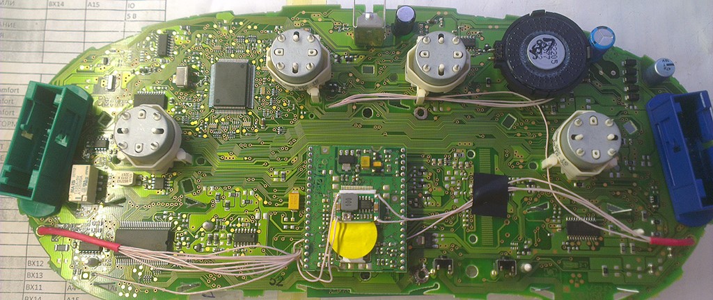
Панель приборов с
Полным БК (fullFIS)
выглядит вот так:
|
|
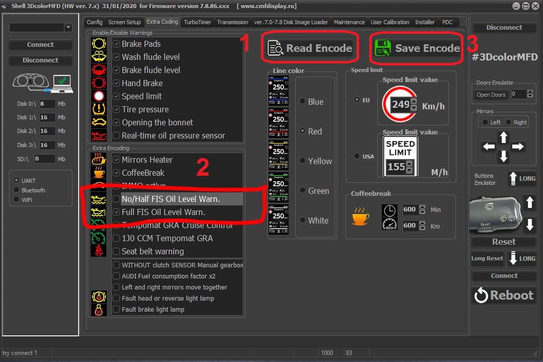
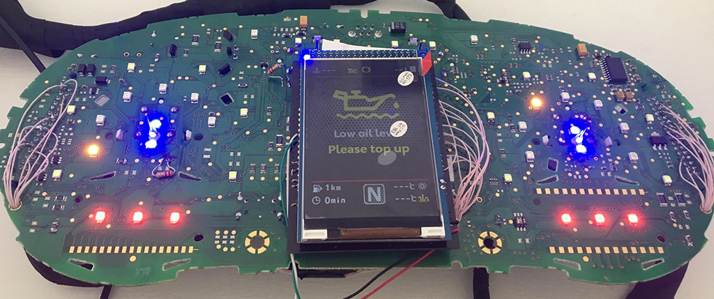
After installation, you need to connect MFD to the Shell program and configure the low oil warning for the FullFIS cluster.
Shell program link:
Video instruction:
https://youtu.be/DEsNmNSrkWM
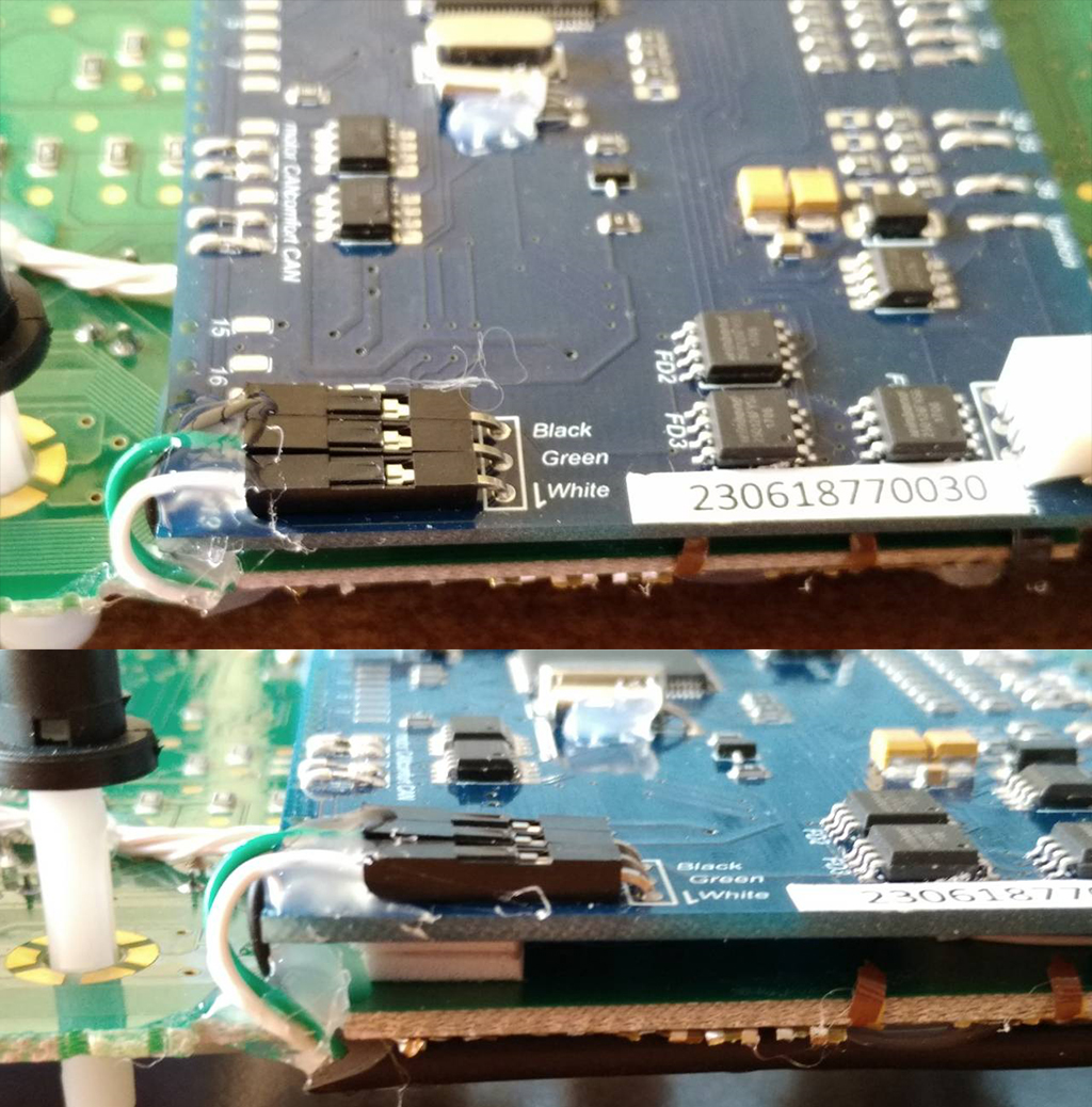
2.5 Lay the wires in such a way that they do not interfere with the installation of white Light diffuser.
| Do not solder these wires! Pins 6 and 7 are spare. |
 |
| 3.1 Cut off Red USB wire, we don`t need it. | 3.2 USB cable should be fixed with glue. | ||
 |
 |
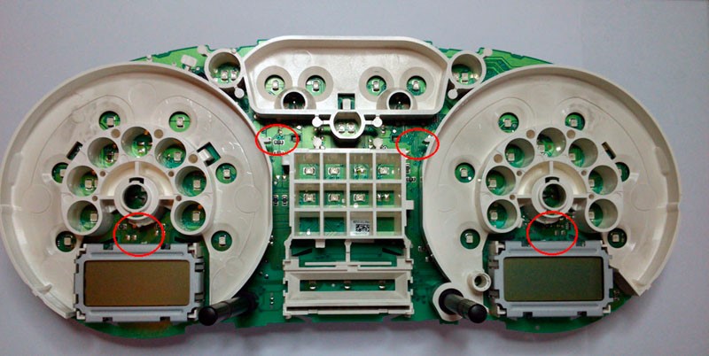
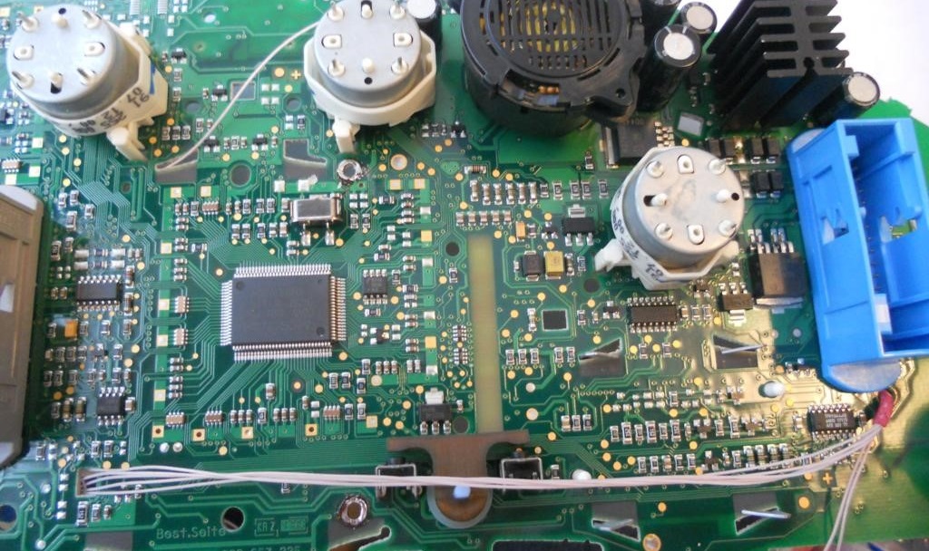
2.6 If you have noFIS or halfFIS dashboard, you need to solder the wire
If you are the lucky owner of Passat B5, released for USA market, you have to add a few SMD resistors to the dashboard.
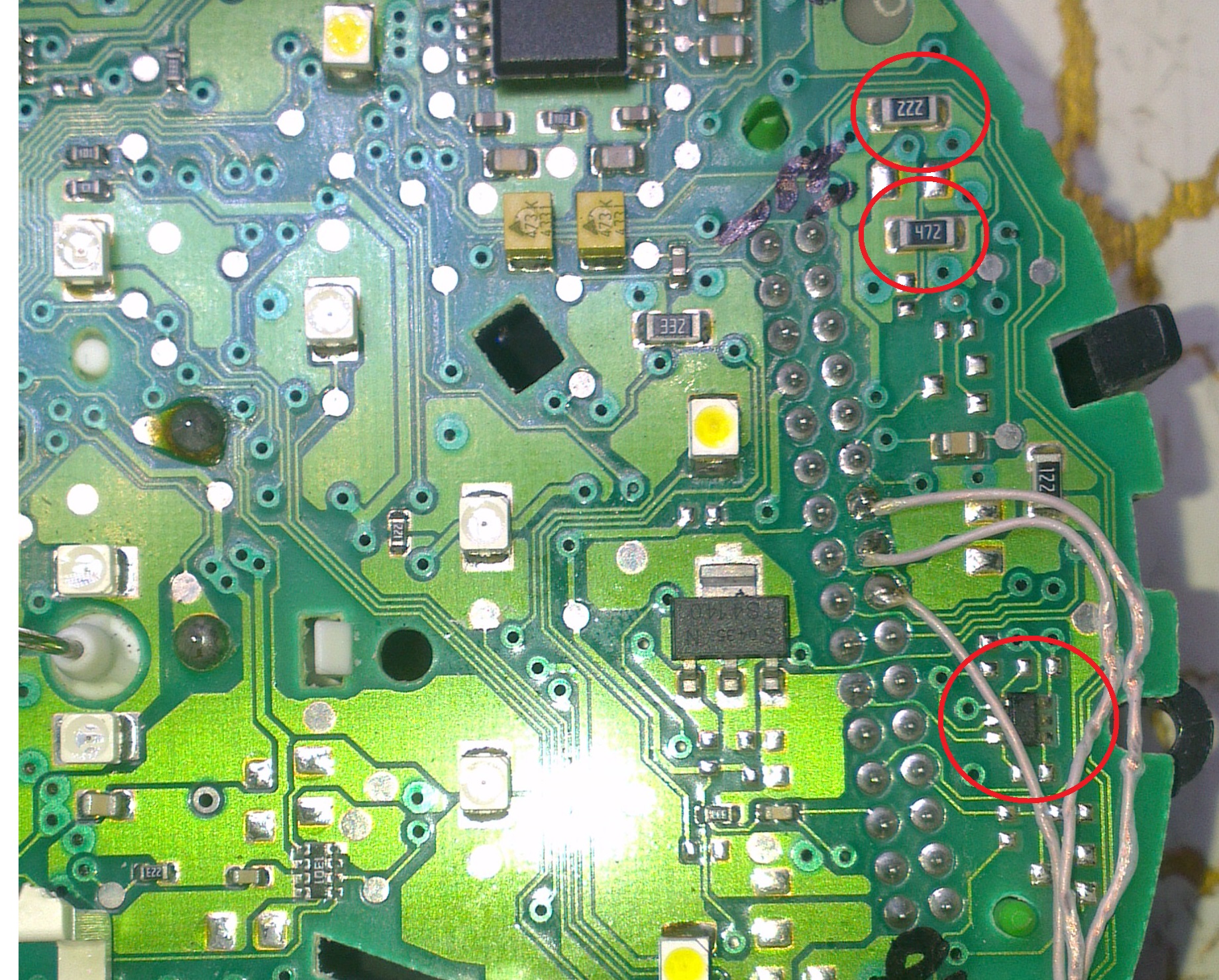
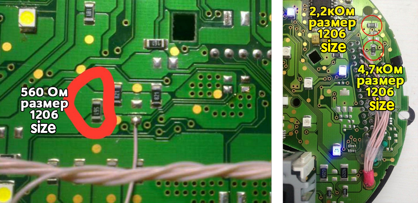
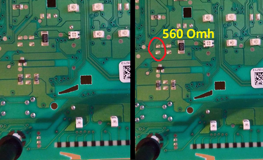
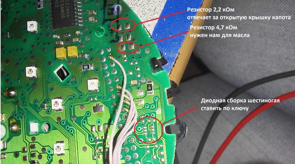
In clusters for the American market, there are no open hood and
oil level control resistors, and there are no oil level and
temperature sensors in the engine sump.
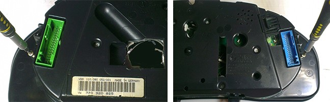
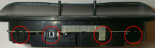
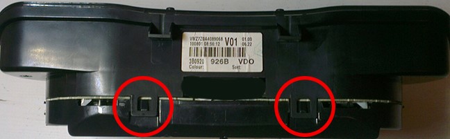
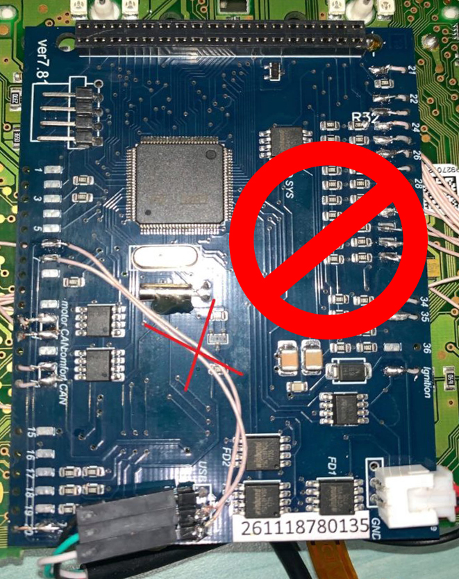
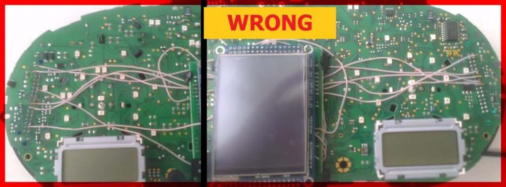
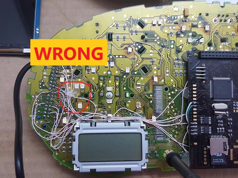
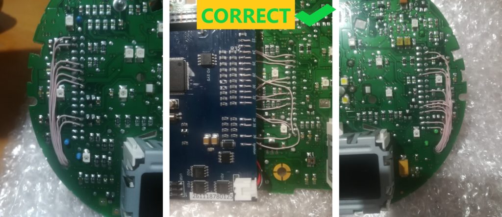
2.7 The wires should be pulled from the back or as shown above.
Wires should not interfere with the assembly of the cluster.
So it's not right!
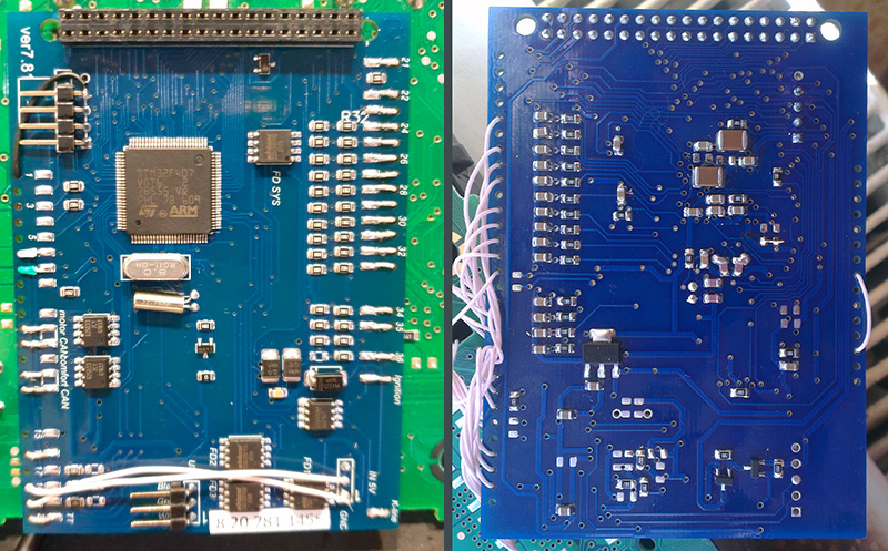
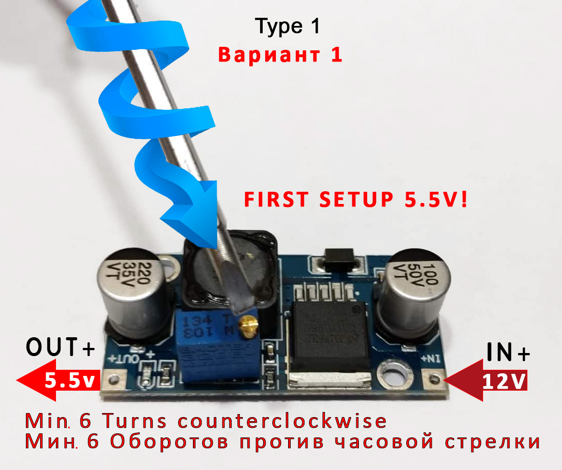
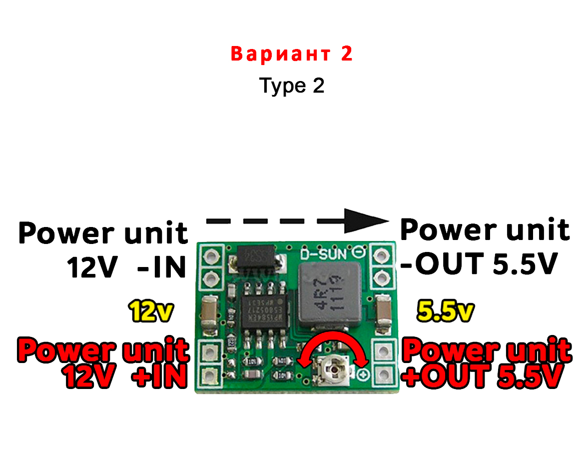
2.8 Power connection
There are two types of power supplies
 |
 |
||
 |
|||
Attention!
Before installing the power supply, you need to solder the wires to its contacts IN+, IN- and OUT+, OUT- ,
then apply a current of 12V to IN+, IN- , and connect the OUT+, OUT- wires to the multimeter.
Now we need to tune the output current. Using a small flat screwdriver, you should rotate tuning resistor
clockwise, until you have 5.5V output voltage on the multimeter.
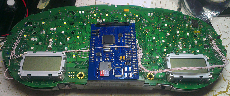
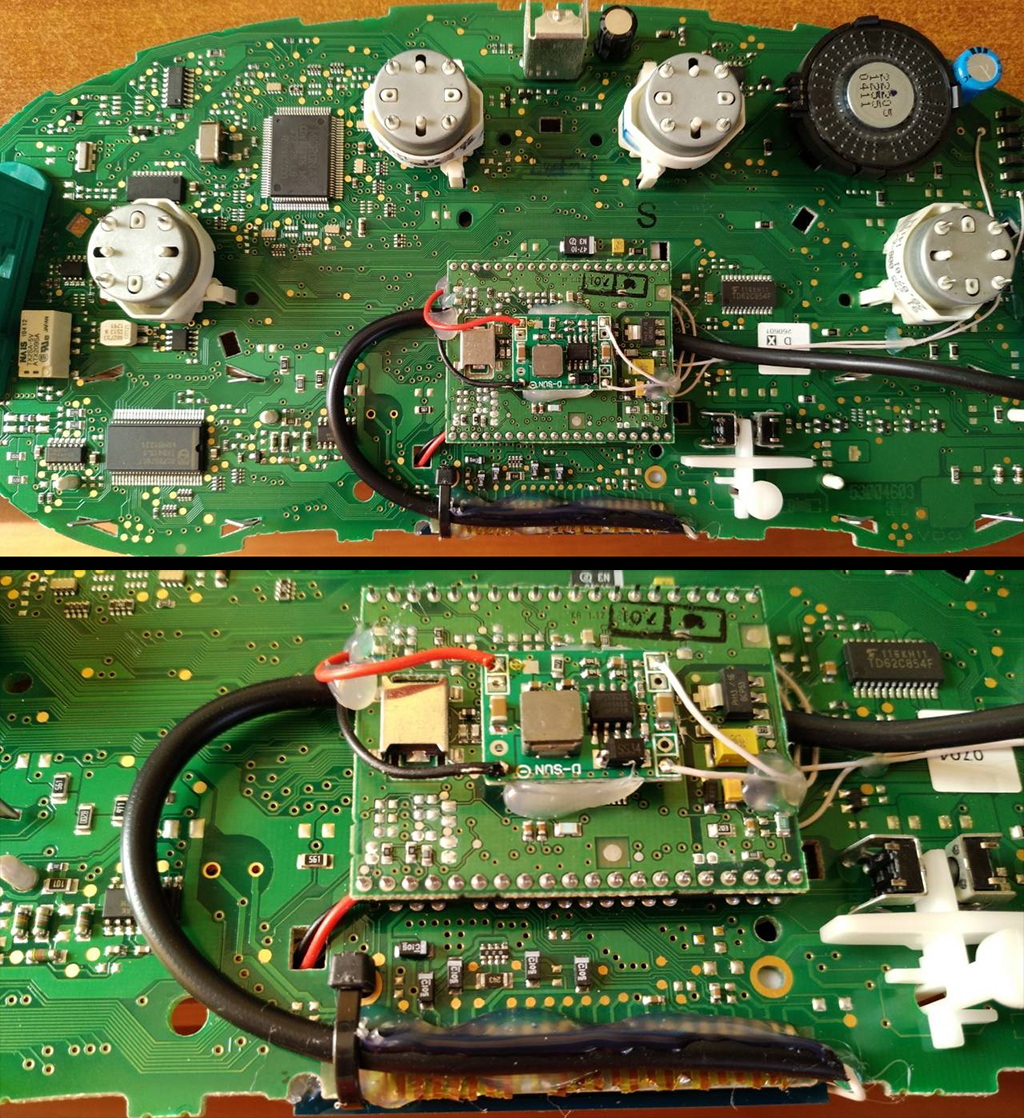
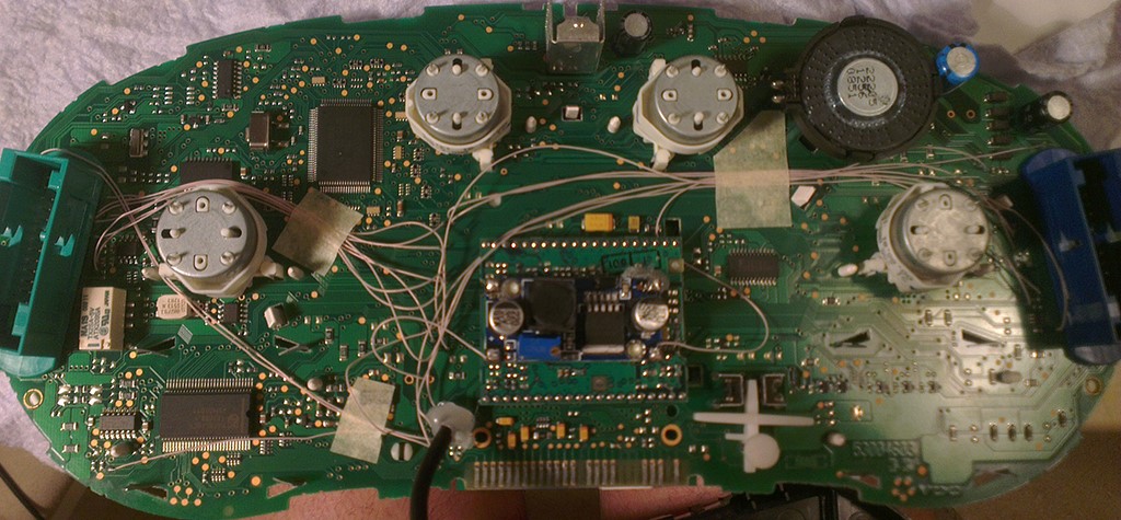
Next, we place the power supply on the cluster`s back board and bring wires from the blue connector to its contacts.
How to do this, look at the connection diagram specifically for your car model.
Choose the installation location of the power supply so that it does not interfere later in the assembly. For example:
Attention!
After wiring, lay it so that they do not interfere with further assembly.
Need to call all contacts and check on the table to avoid confusion anywhere.
2.9 Before assembly, check the functionality of the module in your car.
3. Assembly
After wiring, lay it so that they do not interfere with further
assembly. Check wiring with multimeter, in Diode mode.
On the display, at the back, there is a piece of double-sided tape
(if yours doesn`t have it, attach one). Don`t remove the protective
film from it! We use it only as a support for the display!
|
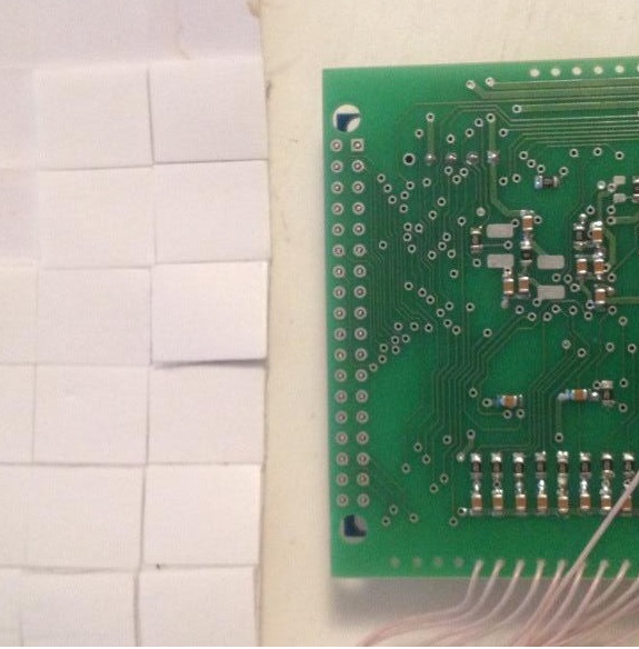
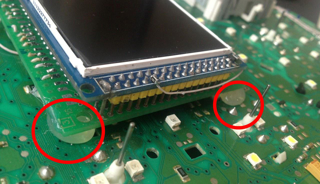
3.3 We take double-sided adhesive tape on a foamy basis, cut the squares 1cm X 1cm.
|
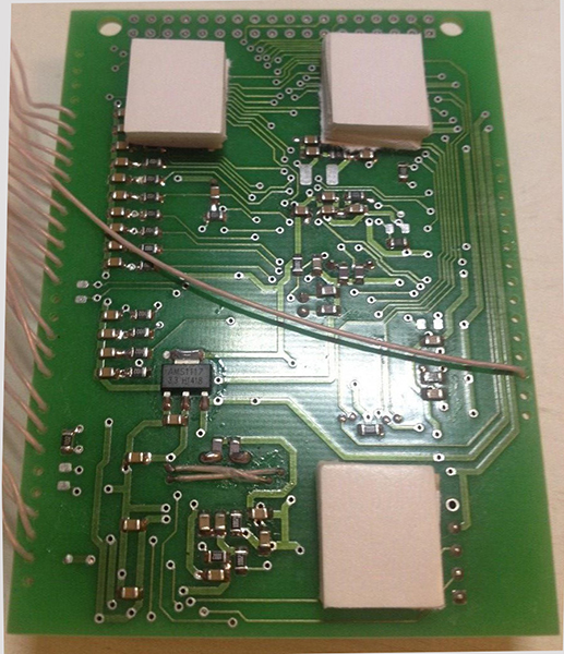
3.4 Collect these squares in 3 floors.
|
||
|
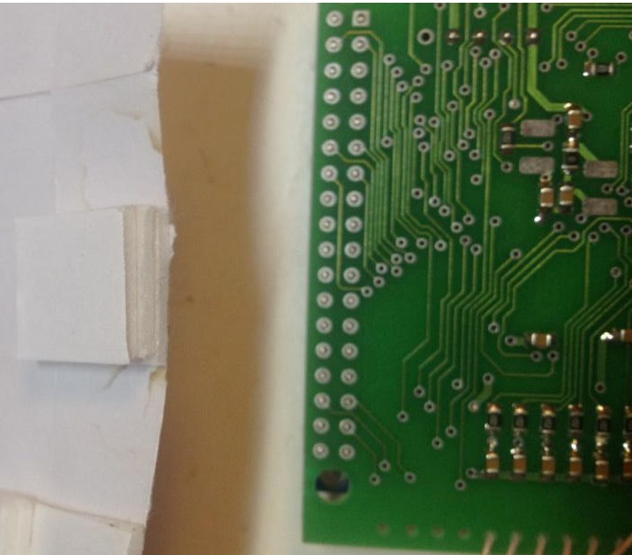
3.5 Place them so that nothing prevents you from mounting the module on the board.
|
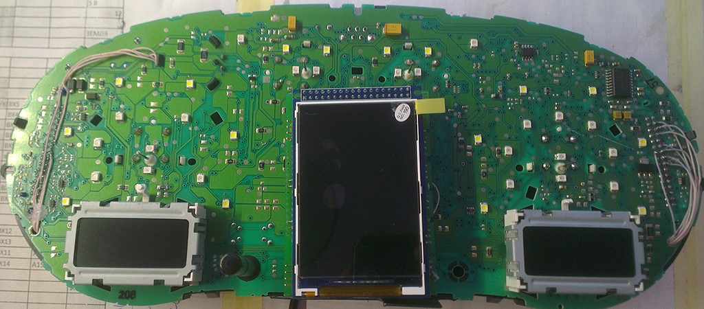
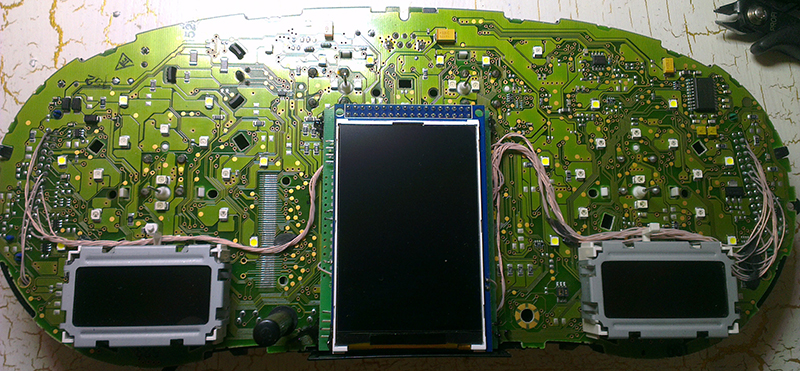
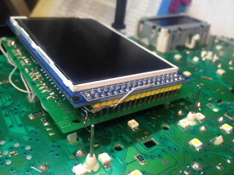
3.6 Place the module so that it fits in the cluster`s window.
|
|
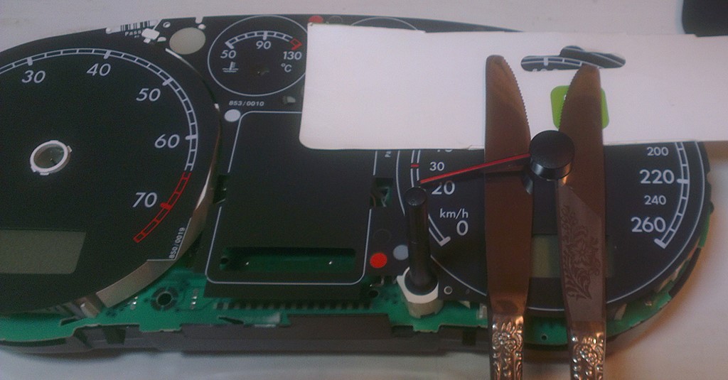
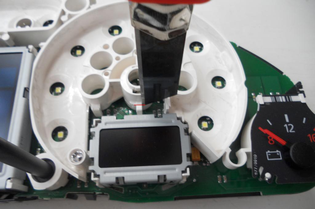
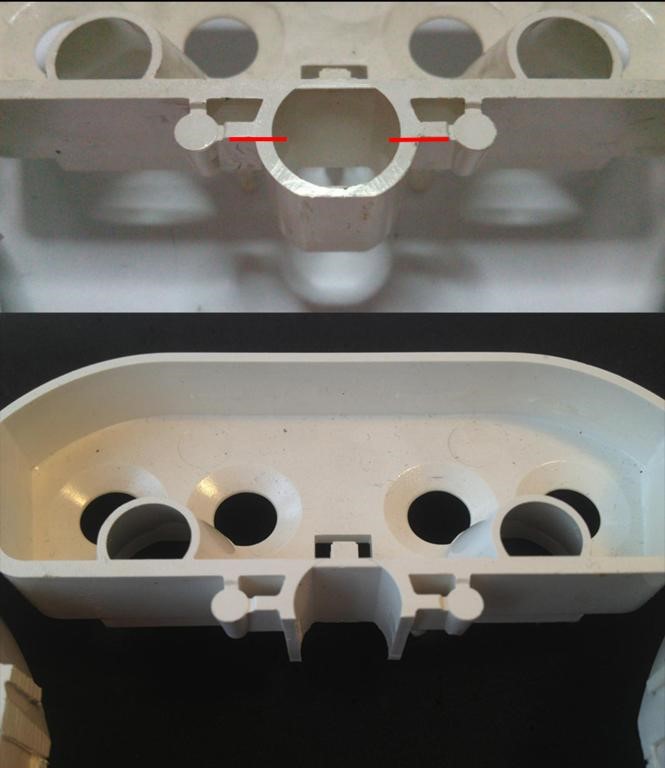
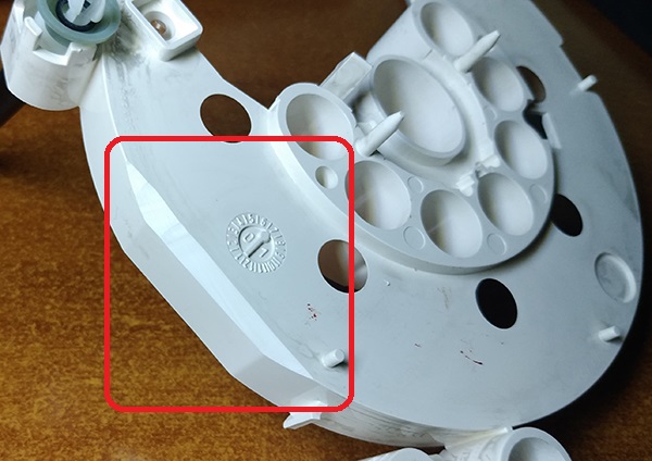
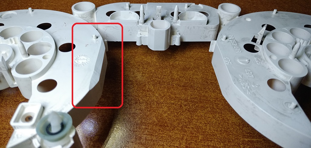
3.7 Cut off the main beam guide part. On the red line. Leave the semicircle.
|
3.8 Cut off the protruding part!
|
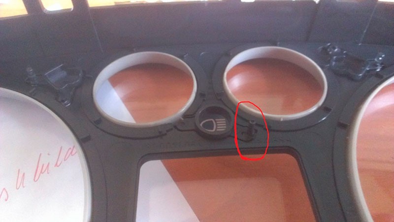
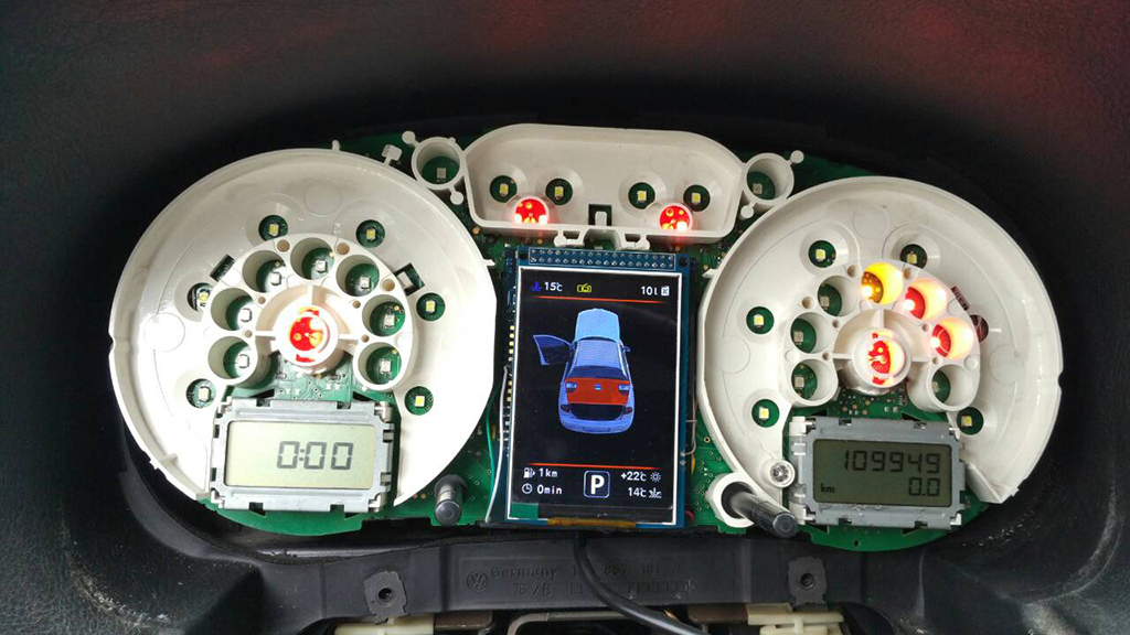
3.9 Install a white diffuser and cut off the excess (as shown in the picture).
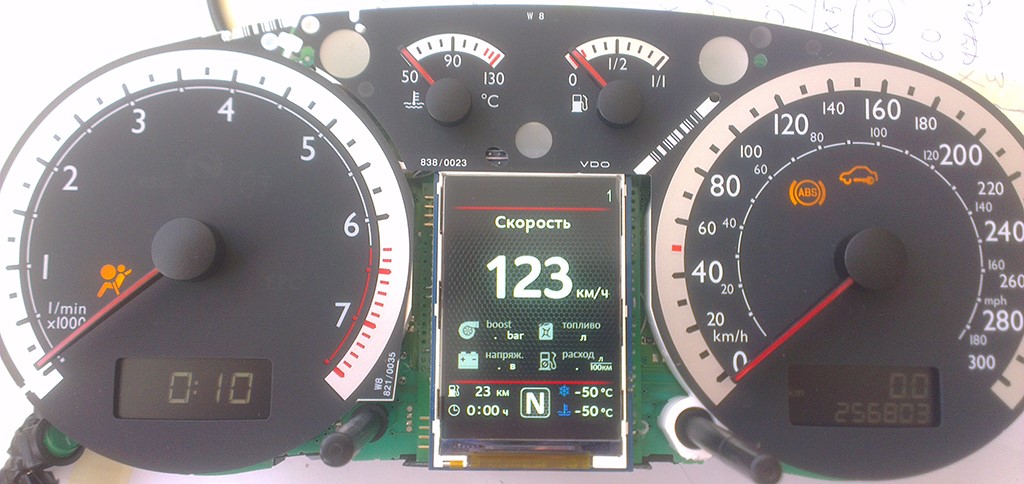
Then place the display and align it so that it clearly fits into the cluster window.
3.10 IMPORTANT! For greater stability, after you have tried and calibrated it, fix its position with hot-melt adhesive.
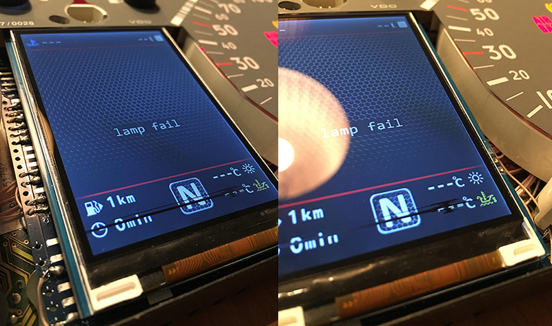
3.11 Next, you need to glue the matte protective film so that the display does not glare in the sun.
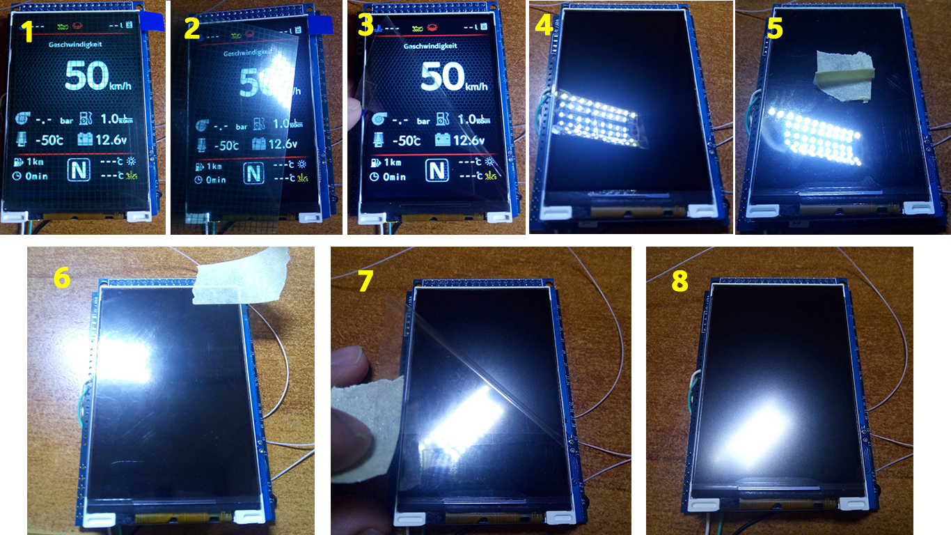
Attention!
Be sure to stick the film!
Otherwise, the display may be damaged!
Using the Shell program to customize the screen frame.
.jpg)
https://youtu.be/DEsNmNSrkWM
|
4. IMMO 2
If you have a 1J0 comfort unit installed. Or
your car is Seat Leon 1M.
|
 |
||
|
|
|||
 |
 |
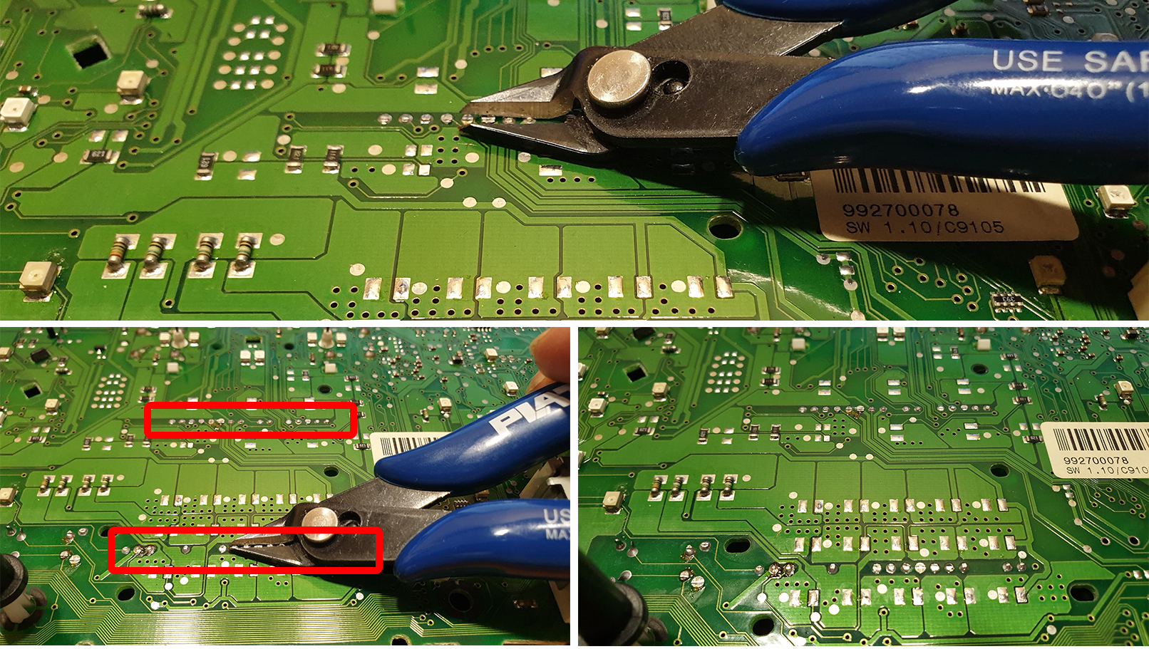
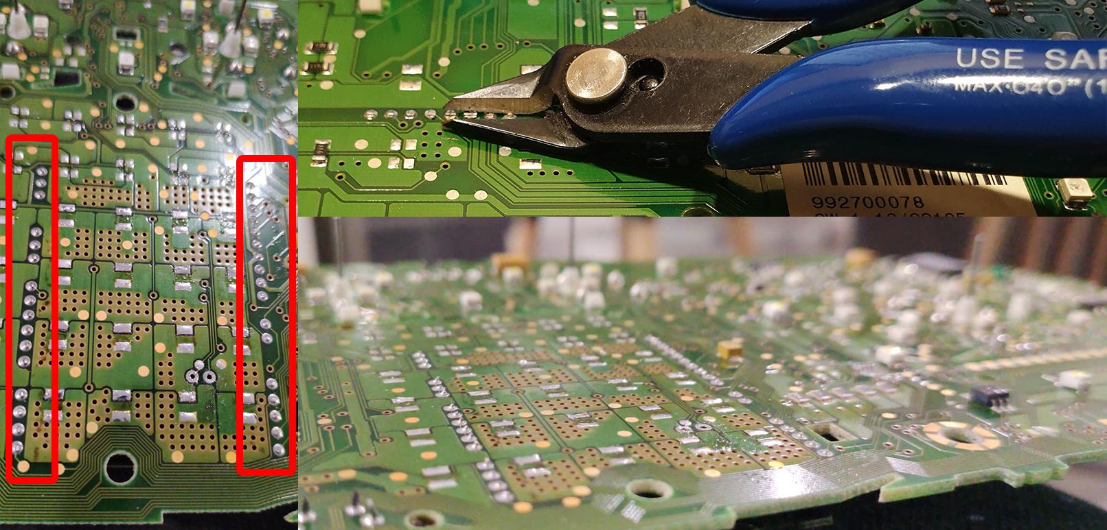
4.1 IMMO3 Cluster Installation in a vehicle with IMMO2
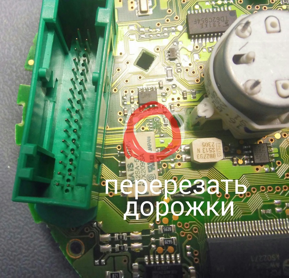
If you are installing IMMO 3 cluster in a car with 1J0 CCMS (comfort unit) —
you shoul remove 2 resistors from the cluster board.
These resistors are coming from 8 and 9 pins of the green connector.
 |
 |
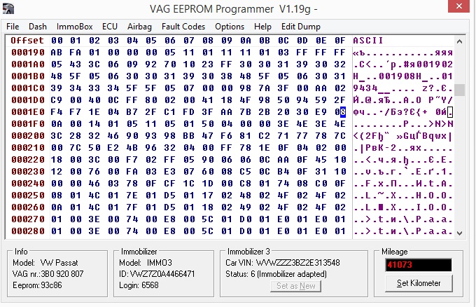
4.2 If you are Installating IMMO3 cluster in a vehicle with IMMO2,
you should activate the ambient temperature sensor in the cluster`s
EEprom.
|
Passat B5 You need to change 1ef from 08 to 01 line 0001E0 column F
|
Golf 4 Cluster 1J0920806G no fis no show temp in dispay You need to change 1e5 from 2B to 2F line 0001E0 column 5
|
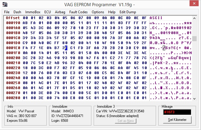
Change 2B in 2F and work
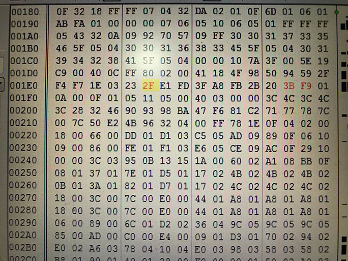
I changed that one 1E0 column 6 from 2B to 2F and it works
5. BOOST
To connect the boost pressure control, You need to add
pin 15 to the green connector.
The other end of the wire must be connected to the engine ECU.
According to the table below, you should find the signal wire of the
boost sensor.
When the engine is idling, the voltage on the wire should be between
1.6 and 1.9 volts.
With an increase in RPM (engine speed), the voltage on this wire should increase.
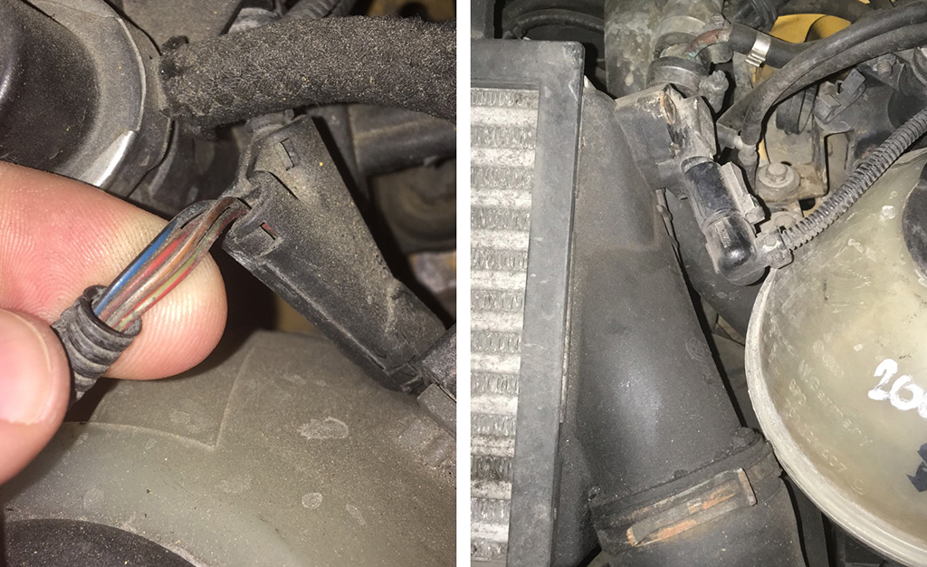
Most often,
On diesel engines (AVB and others):
— 71st pint of ECU, green — red Wire (green with a red stripe);
On petrol (AWM and others):
— 101 pin of ECU, gray — blue wire (gray with a blue stripe).
In general, as I know, in all B5 diesel 1.9Turbo, supercharging is
connected to the 71st pin,
And the gasoline 1.8T is connected to the 101 pin. The color of the
wire can vary depending on the year / engine.
|
 |
 |
 |
||
 |
 |
 |
6. ASSEMBLY
Collect everything in the reverse order, without forgetting to
calibrate the needles with the help of the VAG-com program.
|
6.1 To
do this, connect cluster to the car (without cluster glass) and connect it
with VAG-com.
|
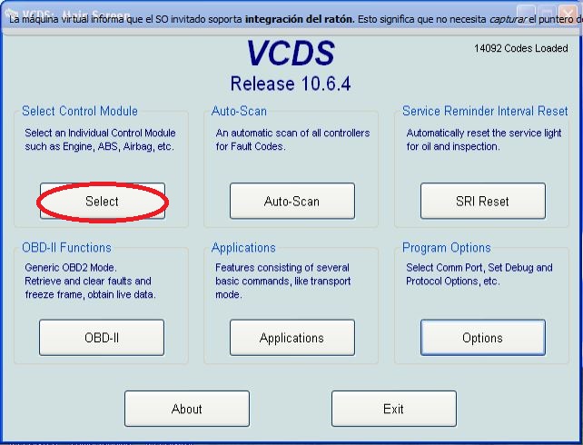
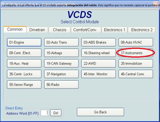
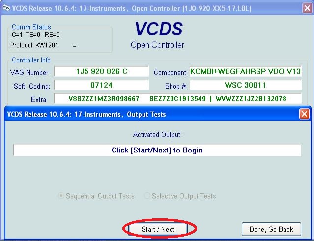
6.2 Go to unit-17.
|
||
|
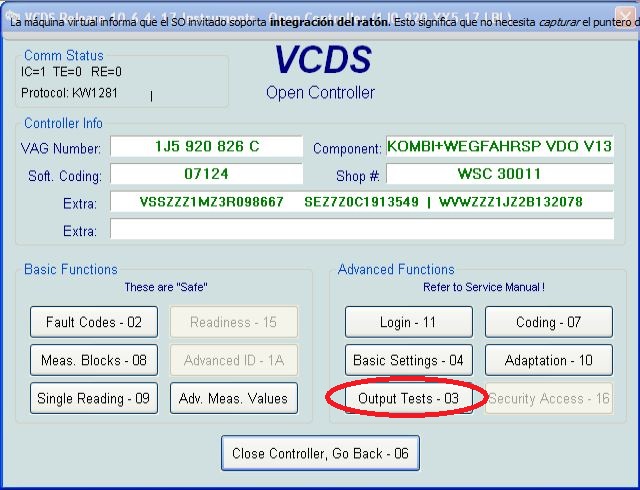
6.3 Select Test unit.
|
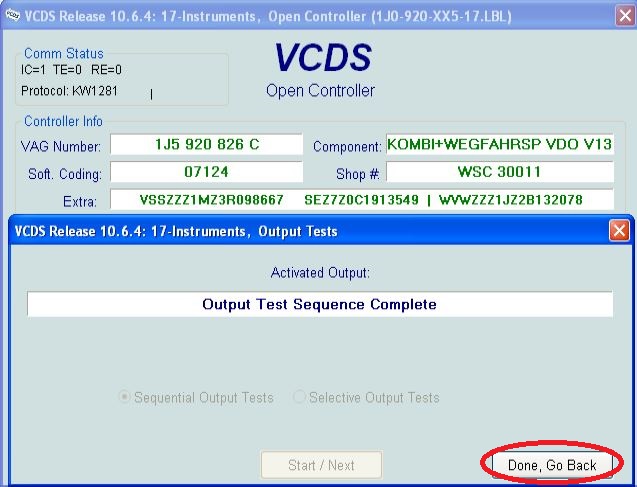
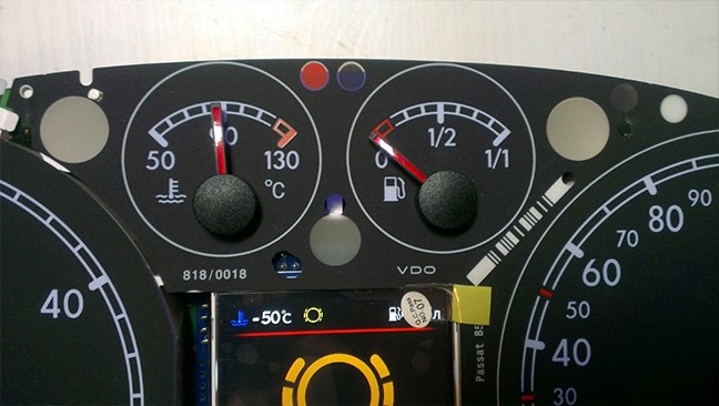
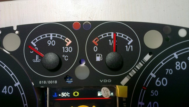
6.4 Make a needle test.
|
||
|
|
|
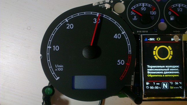
6.6 . Tachometer — 3, 000 RPM.
|
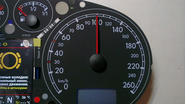
6.8. Speedometer — at 100 km / h
|
||
|
6.9. Coolant temp. — middle
|
6.7 . Fuel level — middle
|
Then check everything
again
You can not turn the needles too quickly correcting the position,
you can damage the motors of the needles
You can not turn the needles, when there is power on the device.
6.6 Put back the cluster glass and put the cluster back into the
car.
7. Take a photo and post it on all social networks.
Go to auto club meeting and brag to your friends.
8. Show it to your girlfriend/wife with words: «Look what a cool
thing I bought for just 20 bucks! » =)