 |
Saprankov |
|
Diaz |
|
Installing
manual |
|
Home
>
Audi - A3
8L, A4 B5. |
3DColorMFD
ver.
7.0.2 |
|
 |
Audi
A3
8L
A4 B5 |
 |
 |
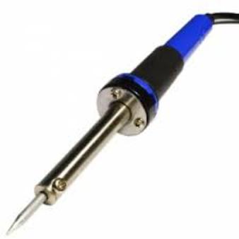
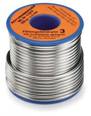
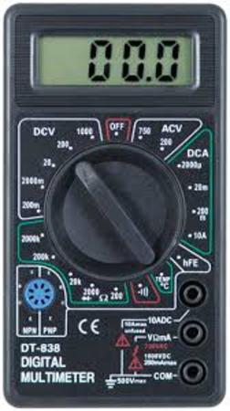
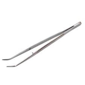
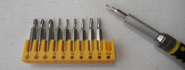
You will need:
|
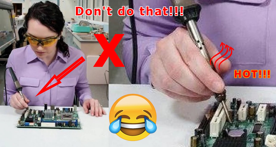
Safety
precautions
DO NOT! |
|
 |
ATTENTION!!!
When installing a color MFD, there are 3 most important points.
1. You need to configure the
power supply to 5.5v.
The MFD operates at a voltage of
5.5v.
When you connect the power supply to the MFD
you should make sure that the output
of the contacts is 5.5v,
otherwise it will damage the processor! Paragraph
18
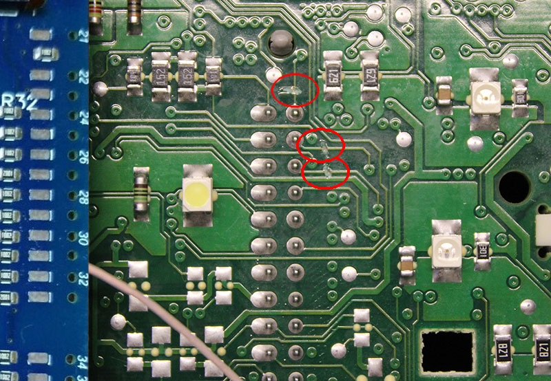
2. It is necessary to cut the
power paths going to the pins 17,18,19,
then check that they are not voltage-free, you need to supply power
to the cluster
and check with a tester, one probe into the ground of the second to
each pin 17,18,19.
Should be 0v . Paragraph
10
3. You need to rinse all the
soldering points. Install very carefully.
After soldering the wires, it is essential to rinse the soldering
points with special flushing agents
or isopropyl alcohol. During washing, do not allow alcohol to enter
the display or under the display and its board!
1.
Disassemble
the cluster.
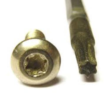
With a
screwdriver torx T10, unscrew the two screws edges
on the rear of the instrument panel.
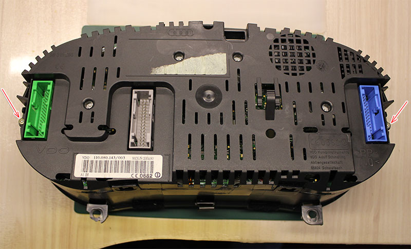
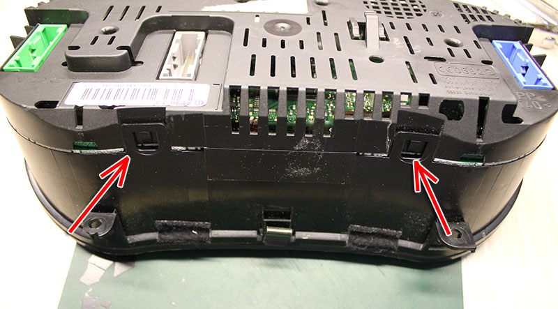
Bend
all the latches neatly remove the front of the case with glass
View from above
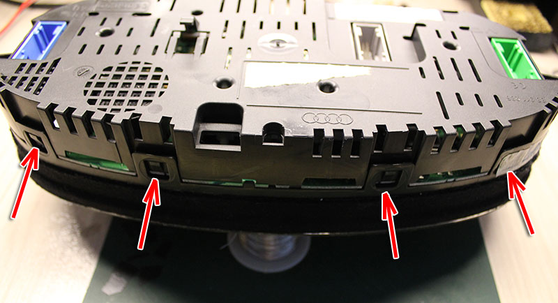
Bottom view
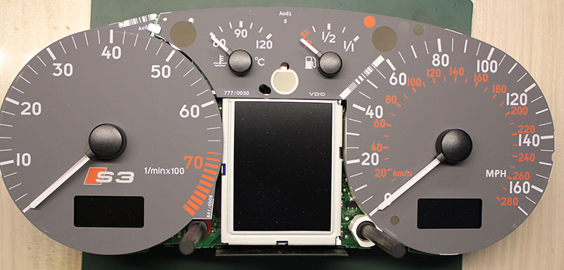
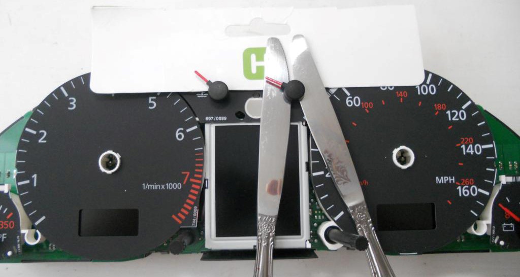
1. Remove
the arrows (scroll counter-clockwise and simultaneously pull
ourselves).
Either Using
knives for oil or spatula, shoot the arrows from their shafts. It
is necessary to put
A
cardboard or napkins between the nomes and the base of the device to
avoid damaging it. Necessary
Pull
the arrows up to yourself.
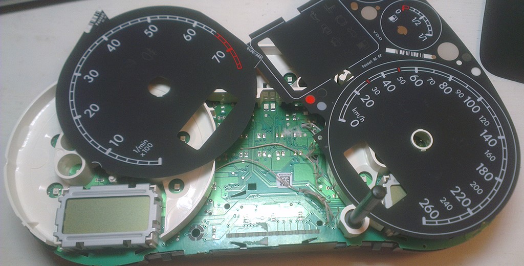
2. Then
remove the substrate.
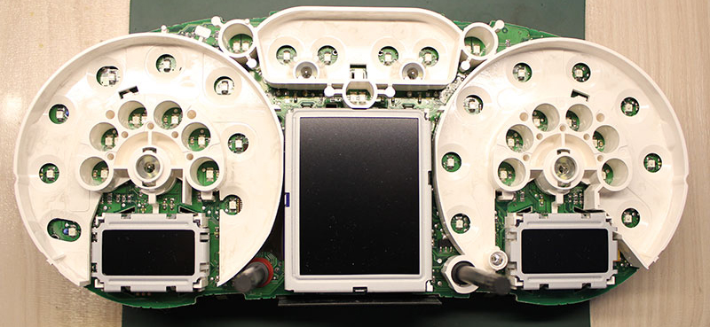
4. Remove the small displays under the speedometer
and tachometer and white plastic.
5. Remove the display
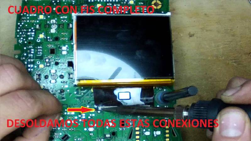
6. Remove
temperature sensor
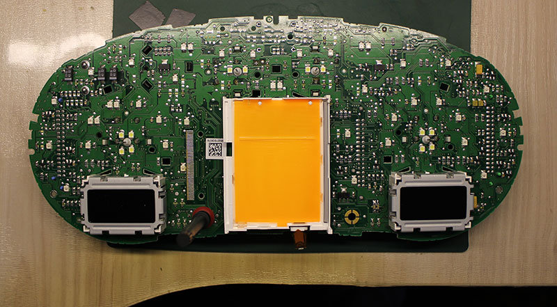
It
should look like this:
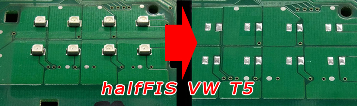
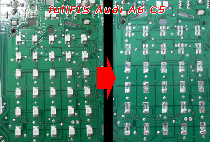
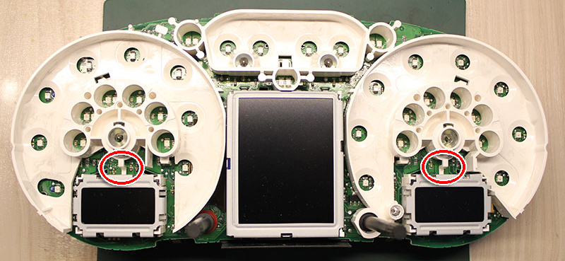
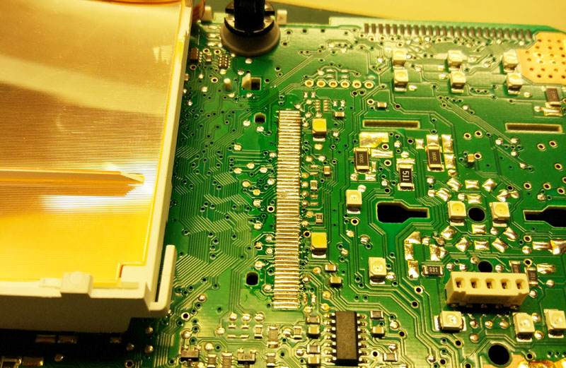
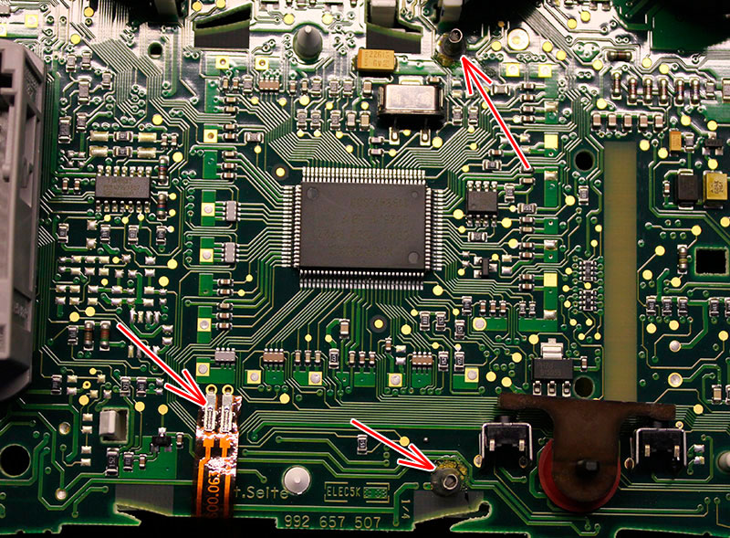
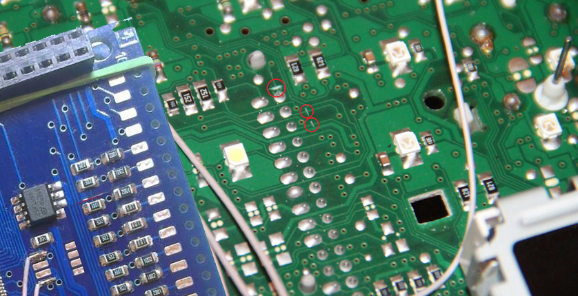
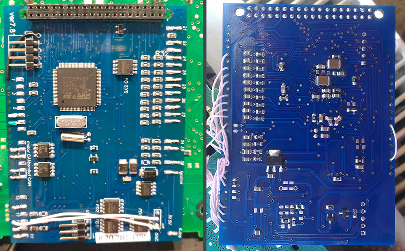
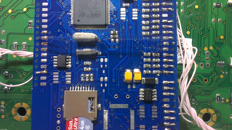
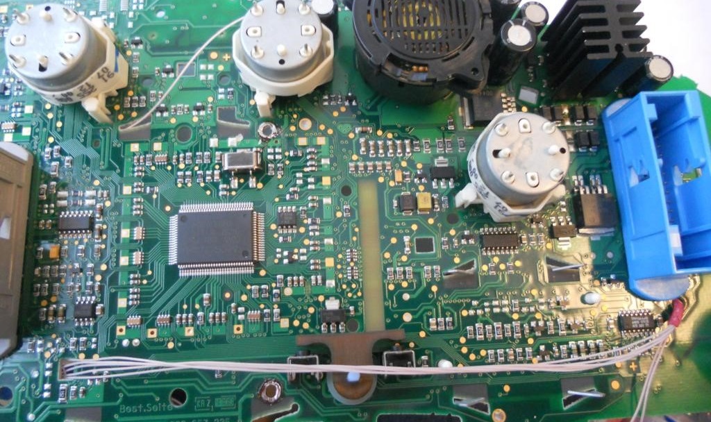
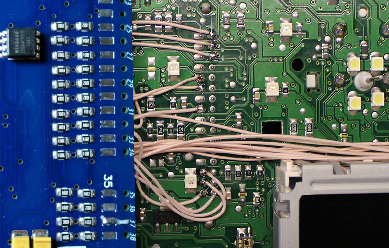
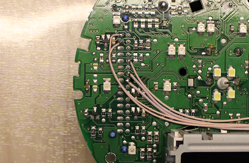
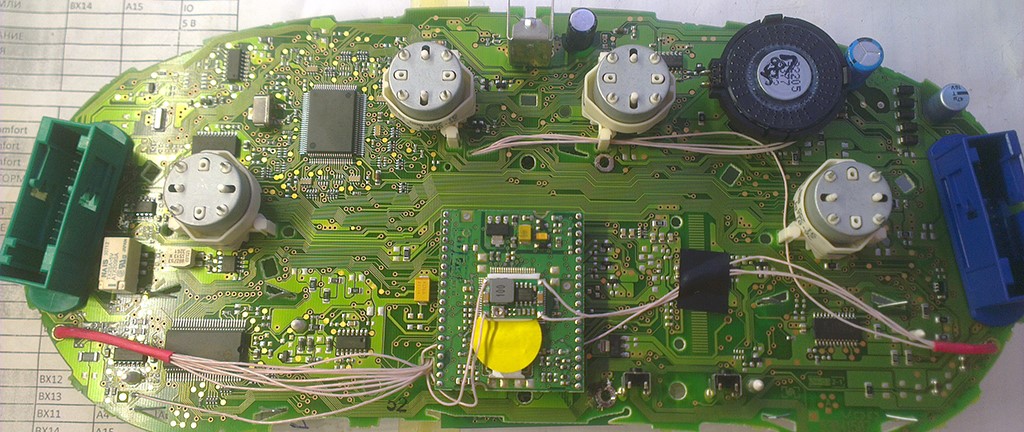
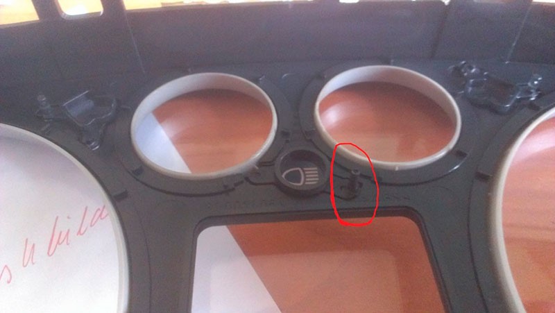
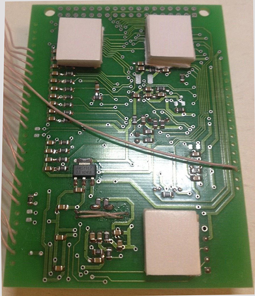
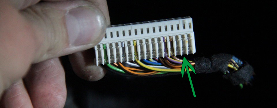
7. VERY IMPORTANT:
For instruments with a BC installed, it
is necessary to
find and trim
tracks from the pins of the control of the standard BC on the
board of the instrument panel (from the pins
8,9,10(doors) and
17,18,19(MFA buttons) of
the grey connector)
AND 21 pin (driver door) of
the blue connector
Below are photos from some instruments.
On your device, the tracks may be located elsewhere
10. We
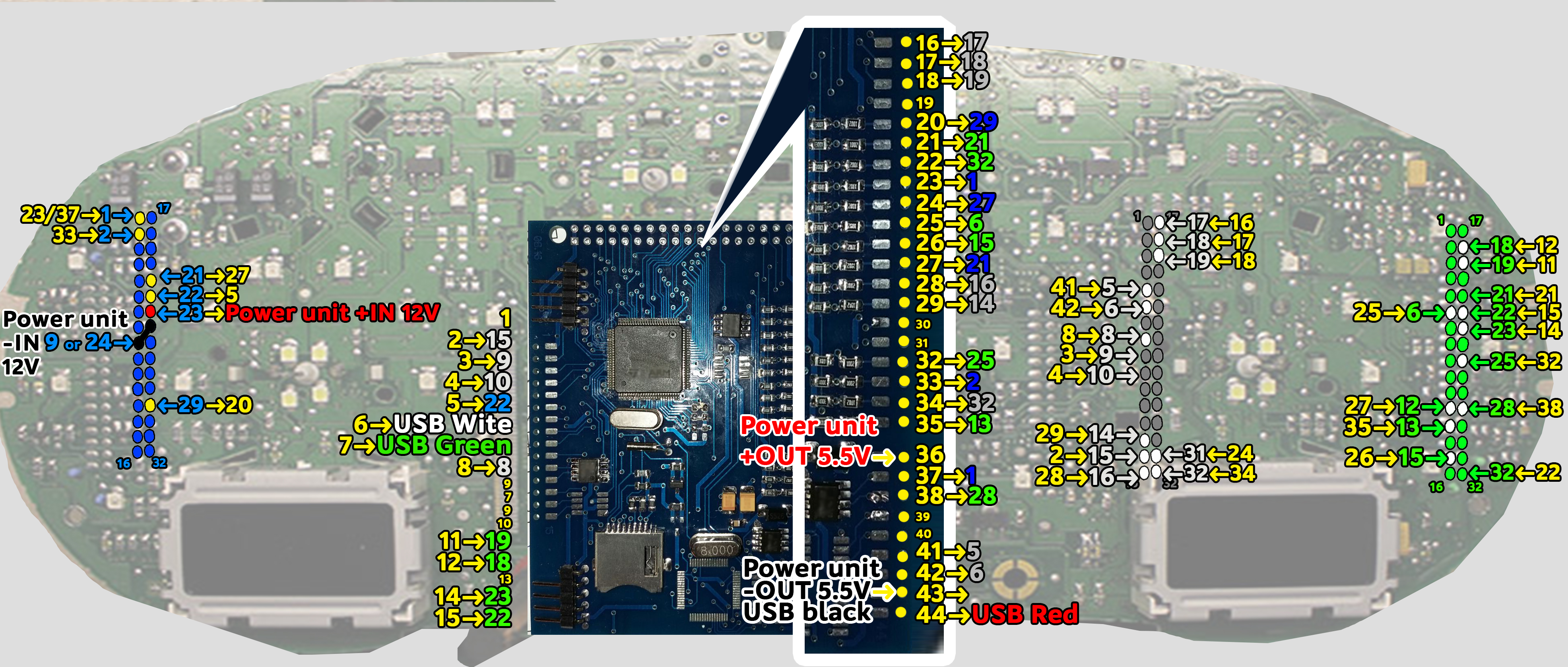
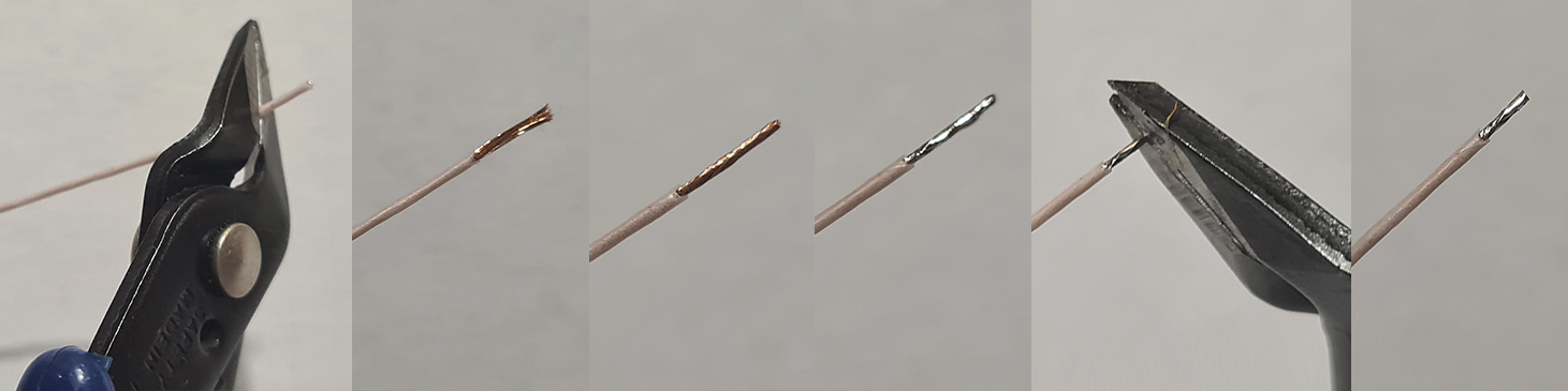
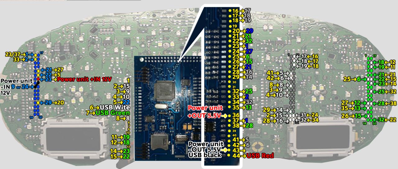
start to build wires according to the table. Wires
are cleaned of
Isolation and
twisting, ludim and cut off excess.
12. Through the
holes in the board of the device, we extend the wires to the blue
And green
connectors.
13. Using the
tester, we find the wires we need and solder them to the feet
Connector
according to the table.
Full size
image

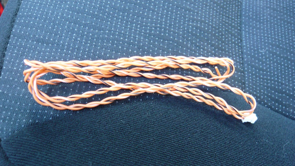
It is necessary to twist the wires of the
connection to the CAN-bus into a spiral.
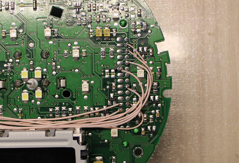
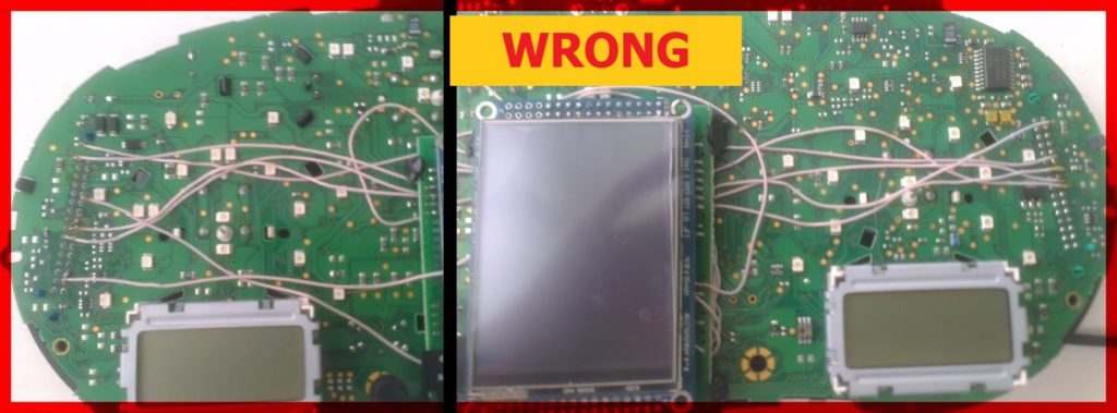
Lay the wires in such a way that they
do not interfere with the installation of white
Light diffuser.
17. Wires should be pulled from the back side Or
as shown above,
So they do not
interfere with the assembly of the device. So
it's not right!
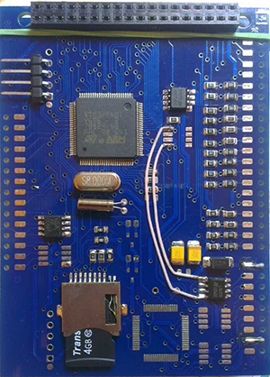
18. Before
installing the power supply, you need to solder the wires to it
Attention!
18. Before
installing the power supply, you need to solder the wires to it
contacts + IN - IN and
+ OUT - OUT ,
then apply a current of 12V to + IN - IN ,
and connect
the + OUT - OUT wires
to the tester.
Now we need to
adjust the output current. Using
a small flat screwdriver
slowly
rotate the special metal knob (figure 1 in the picture.) Clockwise
Arrow, until, at us
on the tester will not appear 5,5v in an output voltage.
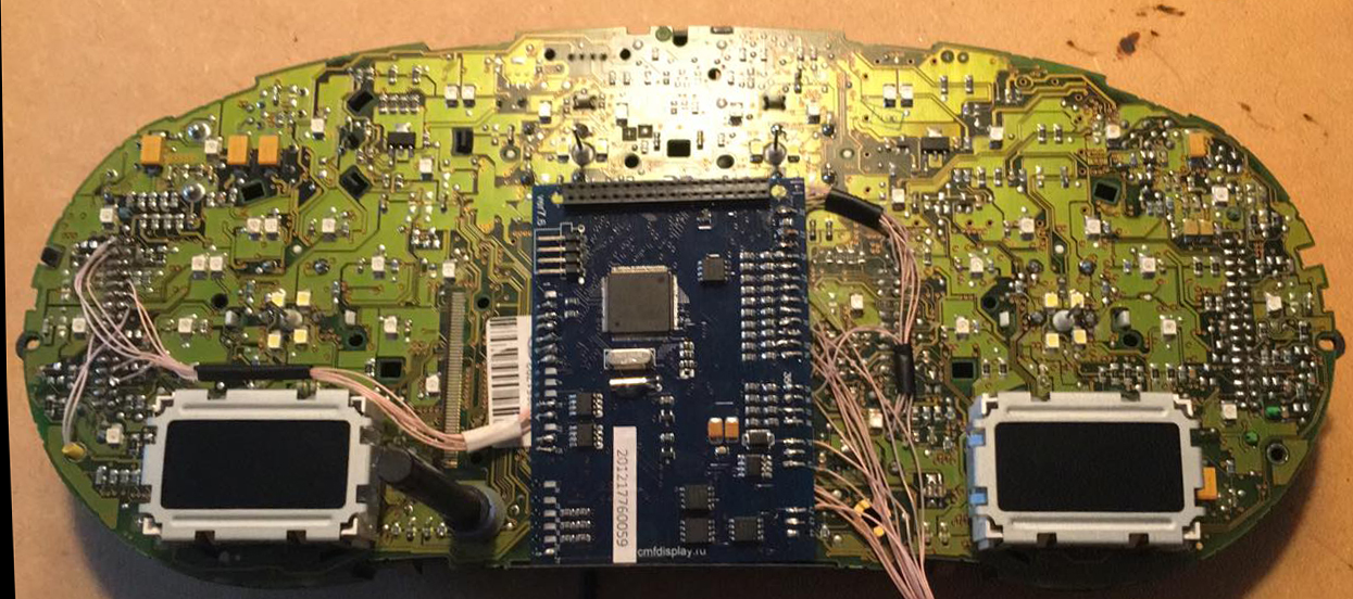
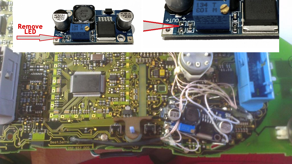
Next we place the
power supply unit on the back side, we bring to its contacts the
wires from the blue connector.
9-pin of the blue connector
is connected to the e - IN on
the power supply board.
23 the leg of the blue connector
is connected to + IN On
the power supply board,
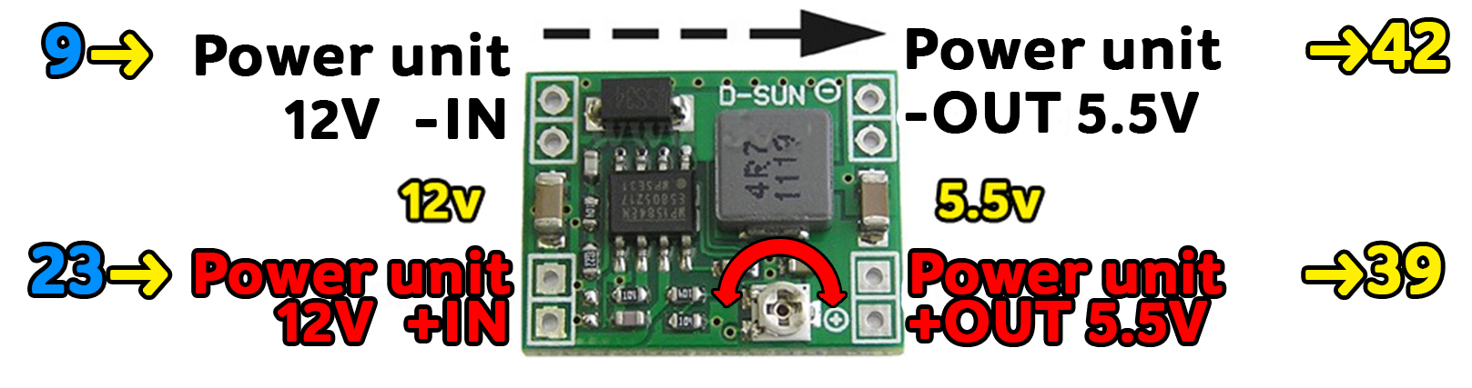
Contact
- OUT Connects
to 42 pin MFD
+ OUT Connects
to the 39 pin MFD,
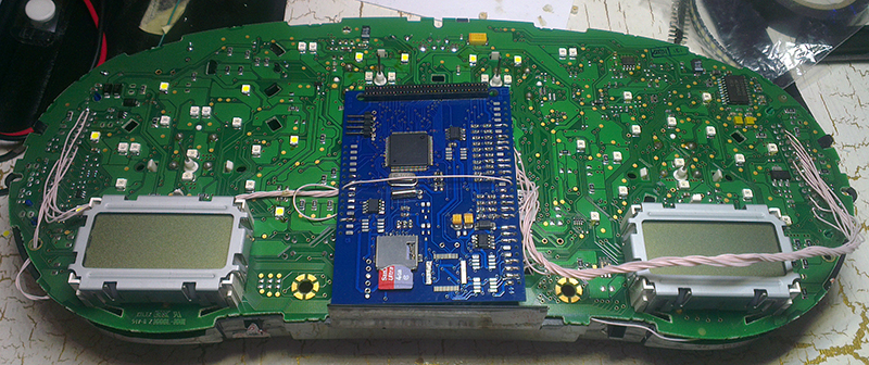
Choose the place of
installation of the power supply so that during assembly it does not
interfere. Here
are the possible
Options:
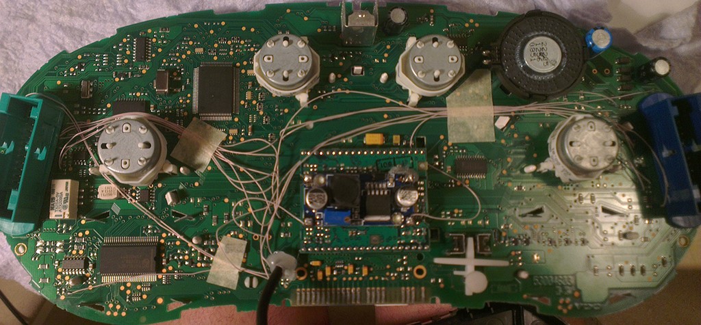
Attention!
After wiring, lay it so that they do not interfere with further
assembly. We call all contacts and check
on the table to avoid confusion anywhere.
20. Cut off the
main beam guide part.
On the red line.
Leave the
semicircle.
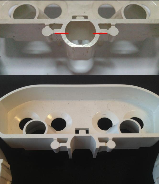
21.
Bite off the protruding part!
22. Before
installing the display, you need to glue two-way
cattle into three
layers on the back of the display to lock the display.
Attention, you do not need to attach modules to the board!
It is enough simply to remove an additional support from a
double-sided adhesive tape
without removing the protective layer
from the side of the module board.
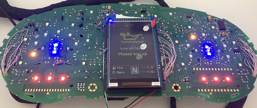
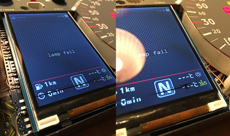
After you solder the wires
and set the display to its place, you need to test the MFD's
performance in the car to make sure everything is properly installed
and working well.
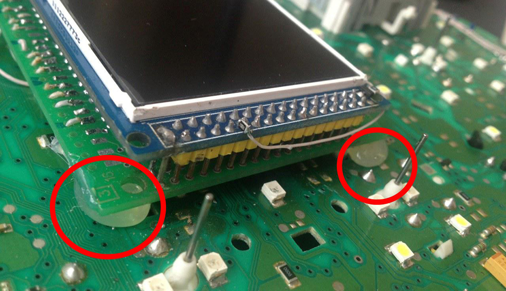
23. We take
double-sided adhesive tape on a foamy basis, cut the squares 1cm X 1cm.
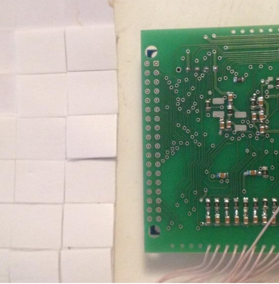
24. We collect
these squares in 3 floors.
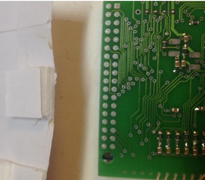
25. And we place
them so that we do not have anything to do with mounting the module
on the board
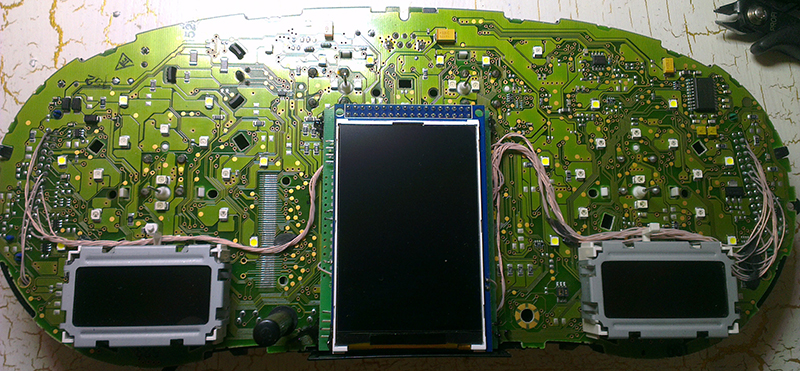
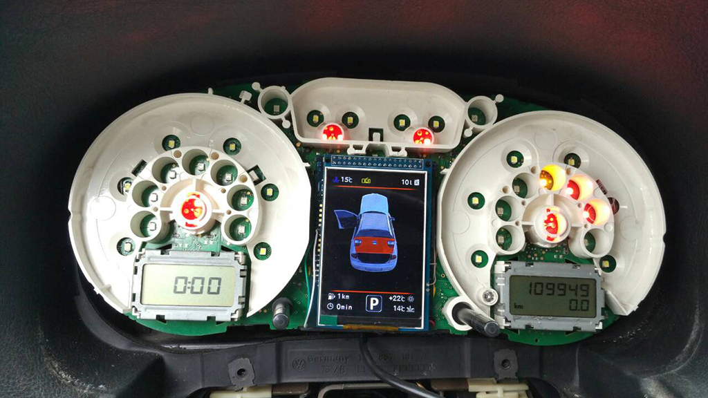
26. Place the
module so that it is placed in the window of the device
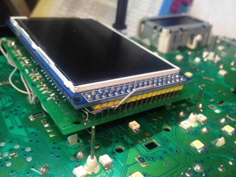
27. For greater reliability, when the module is already installed on
the board, and you calibrated it in the window so that there were no distortions, it is
better to fix it.
Its hot glue along the edges of the module.
After you solder the wires
and set the display to its place,
you need to
test the MFD performance in the car to make sure everything is properly installed
and working well.
23. We take
double-sided adhesive tape on a foamy basis, cut the squares 1cm X 1cm.
24. We collect
these squares in 3 floors.
25. And we place
them so that we do not have anything to do with mounting the module
on the board
26. Place the
module so that it is placed in the window of the device
27. For greater reliability, when the module is already installed on
the board,
and you calibrated it in the window so that there were no distortions, it is
better to fix it.
Its hot glue along the edges of the module.
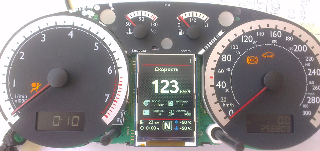
Next, you need
to glue the matte protective film so that the display does not glare
in the sun.
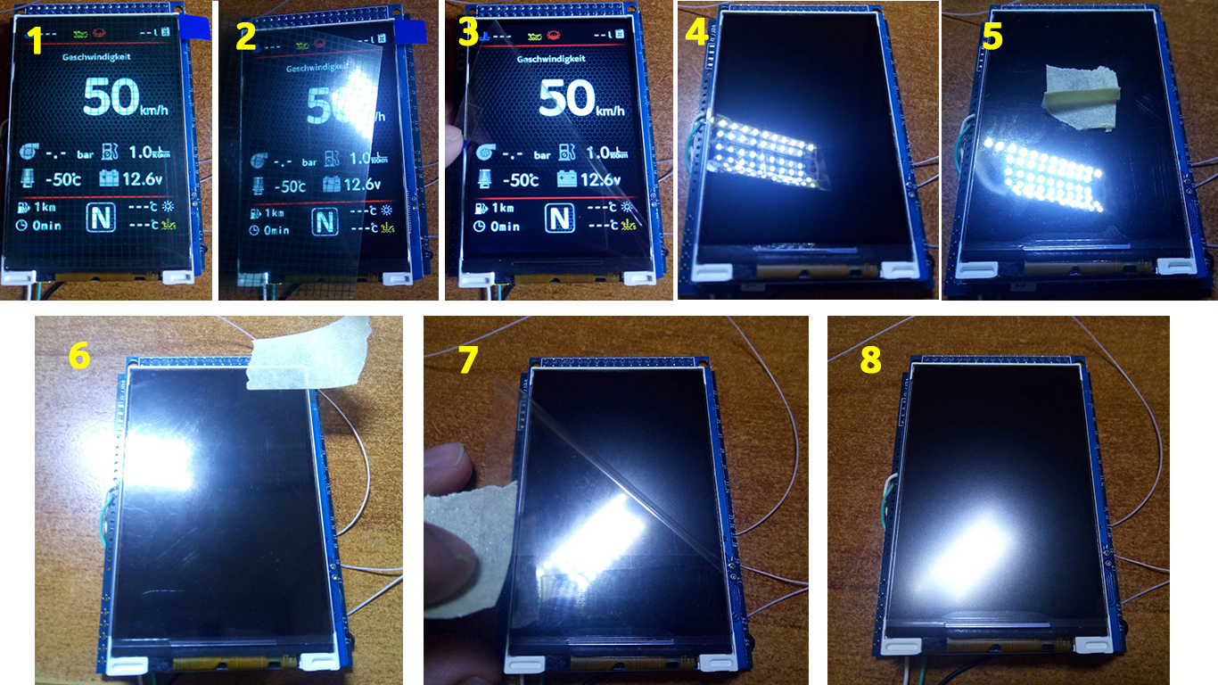
Attention!
Be sure to stick the film!
Otherwise, you may damage the display!
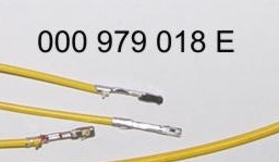
T
o connect the boost pressure control.
You will need to add one PIN to the dashboard
32 pin
grey connector.
And the second end of
the wire needs to be connected
the signal wire of
boost sensor,
on this wire at idle should be 1.6v,
with increasing PRM the voltage should
increase.
If your motor is not in the table, find the boost sensor under the
hood, it has 4 wires,
Use a multimeter to determine the signal wire, remember its color
and find this wire in the ECU connector
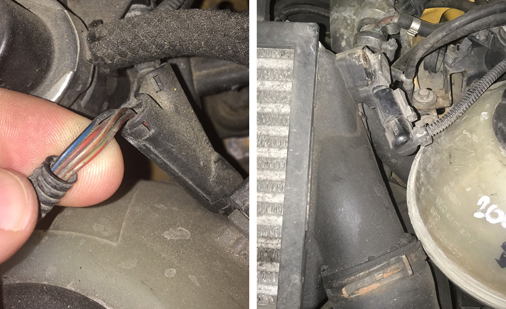
Usually it is blue - gray wire
(blue with a gray bar) to the incoming
On the 101st contact of a smaller brain connector.
On
diesel engines (AVB and others):
- 71st
contact of the motor
brain, green - red Wire
(green with a red stripe).
On
petrol (AWM and others):
- 101st
contact of the motor
brain, gray - blue wire
(gray with a blue stripe).
In
general, as far as I understand, at all B5-x diesel 1.9T
supercharging is connected to the 71st
And
the gasoline 1.8T is connected to the 101st contact. The
color of the wire can vary depending on the year / engine.
|
BES |
2.7T |
T121 |
101 pin |
blue-gray |
|
AJM |
1.9TD |
T121 |
71 pin |
yellow-black |
|
AKN |
2.5TD |
T121 |
71 pin |
yellow-red |
|
AUY |
1.9TD |
T121 |
71 pin |
yellow-black |
|
BQW |
2.0TD |
T94 |
78 pin |
green-red |
|
AWT |
1.8T |
T121 |
101 pin |
blue-gray |
|
AVG |
1.9TD |
T80 |
40 pin |
yellow-green |
|
AWM |
1.8T |
T121 |
101 pin |
blue-gray |
|
AFN |
1.9TD |
T121 |
70 pin |
green-red |
|
AWD |
1.8T |
T121 |
101 pin |
blue-gray |
|
AVB |
1.9TD |
T121 |
71 pin |
green-red |
|
AWP |
1.8T |
T121 |
101 pin |
violet-gray |
|
AVF |
1.9TD |
T121 |
71 pin |
green-red |
|
AUM |
1.8T |
T121 |
101 pin |
violet-gray |
|
AWX |
1.9TD |
T121 |
71 pin |
green-red |
|
AUQ |
1.8T |
T121 |
101 pin |
violet-gray |
|
AHF |
1.9TD |
T121 |
71 pin |
yellow-black |
|
ARZ |
1.8T |
T121 |
101 pin |
violet-gray |
|
ALH |
1.9TD |
T121 |
71 pin |
yellow-black |
|
ARX |
1.8T |
T121 |
101 pin |
violet-gray |
|
ARL |
1.9TD |
T121 |
71 pin |
yellow-black |
|
ANB |
1.8T |
T121 |
101 pin |
blue-gray |
|
ASV |
1.9TD |
T121 |
71 pin |
yellow-black |
|
APU |
1.8T |
T121 |
101 pin |
blue-gray |
|
ASZ |
1.9TD |
T121 |
71 pin |
yellow-black |
|
APB |
1.8T |
T121 |
101 pin |
blue-gray |
|
ATD |
1.9TD |
T121 |
71 pin |
yellow-black |
|
AMB |
1.8T |
T121 |
101 pin |
blue-gray |
|
AXR |
1.9TD |
T121 |
71 pin |
yellow-black |
|
|
|
|
|
|
|


And then we collect everything in
the reverse order without forgetting
to calibrate the
needles
with the help
of the WAG-com.
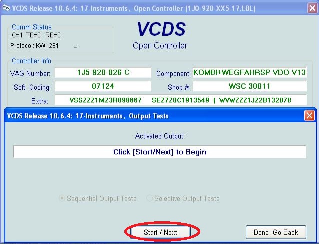
I. To
do this, connect the device to the machine without installing the
glass, connect the VAG-com,
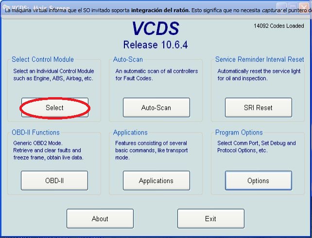
Ii. Go
into the 17-unit dash panel
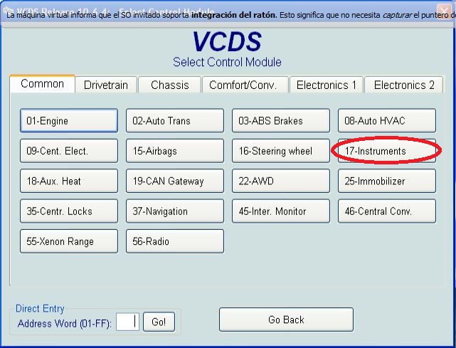
Iii. Select
test performers.
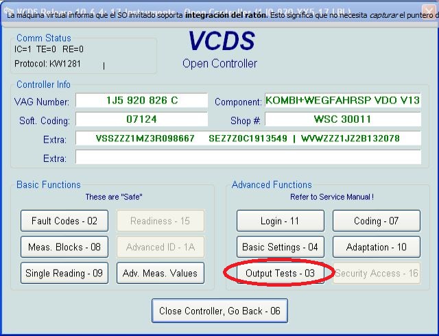
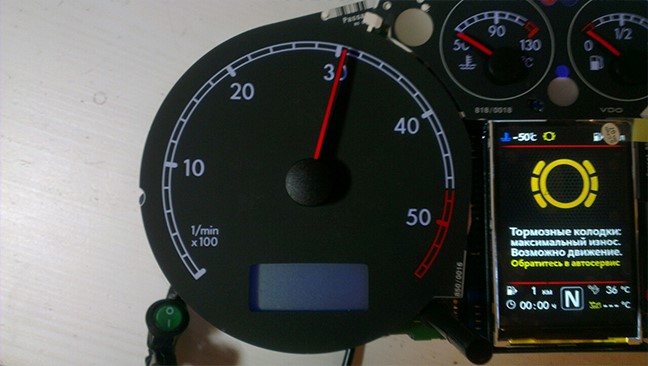
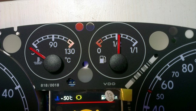
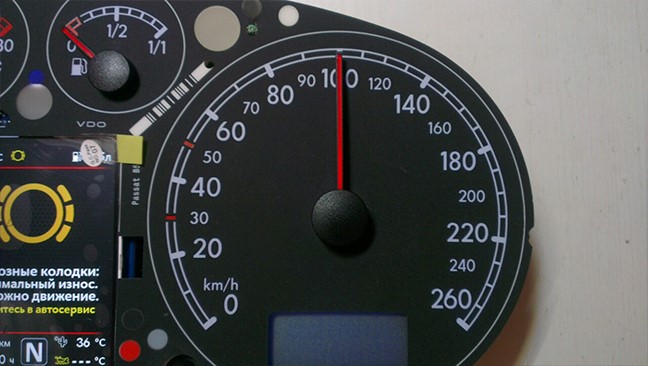
Iv. Choosing
in turn a tachometer, temperature and the rest, the arrows in turn
will be
Do a turn on
the whole scale, and then freeze on:
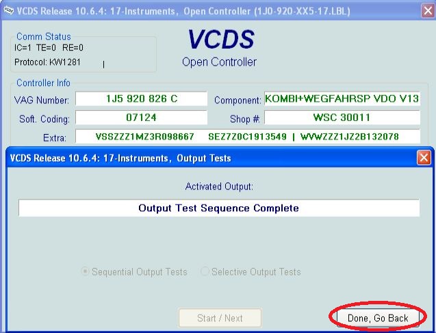
1. Tachometer
- 3 thousand revolutions
2. Pace. Coolant
- middle
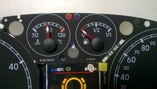
3. Fuel
level - middle
4. Speedometer
- at 100 km / h
V. Then
turn off the power from the device!
Vi. And
set the arrows correctly rotating them in the desired direction.
Vii. Then
check everything again
Viii. You
can not turn the needles too quickly correcting the position, you can
to
damage the motors of the
needles
Ix. You
can not turn the arrows when there is power on the device.