0.1 Before starting the installation, you
need to change the coding of your dashboard and disable the transition to
the internal menu of the original display to avoid false alarms and blind
control of the OEM display. Since you simply remove the original display but
the dashboard will still work.
To do this, you need to do all the internal menu settings that you want,
because then they will not be available, and the menu 3dMFD is not connected
to the menu of the original display.
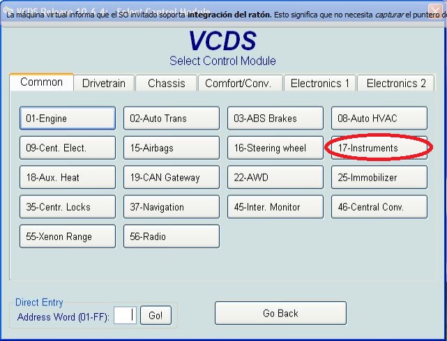
Also the VCDS program
17-dashboard
Coding - 07 ????xxx
+0002 Highline without DIS
Adaptation - 10 Channel 82
change 2 to 0
0.1. Перед началом установки нужно сменить
кодирование вашей приборной панели и отключит ьпереход во внутреннее меню
оригинального дисплея ,что бы избежать ложных срабатываний и управления
штатным дисплеем в слепую. Так как вы просто удалите оригинальный дисплей но
приборная панель по прежнему будет работать. Для этоговам нужно сделатьвсенастройки внутреннего меню,
которые вы хотите, потому что потом они будут не доступны, а меню
3dMFD не связано с меню оригинального дисплея.
А так же программа VCDS
17-панель приборов Кодироваине - 07
????xxx
+0002 Highline without DIS
Адаптация - 10
Channel 82
изменить 2 на 0
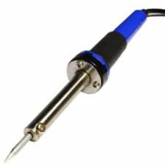
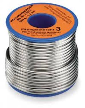
You will need:
Soldering iron 40W
Tin
Flux
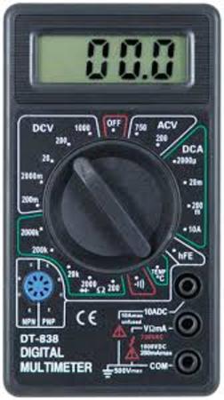
Multimetr
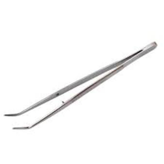
Tweezers
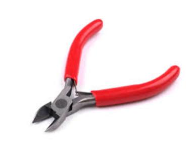
Nippers
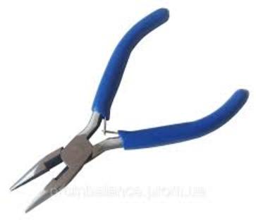
Pliers
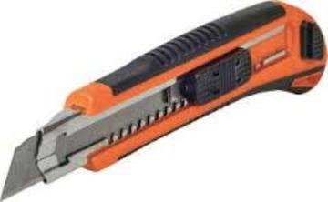
Knife
Thermocouples
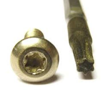
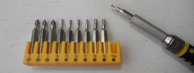
And screwdriver Torx T10
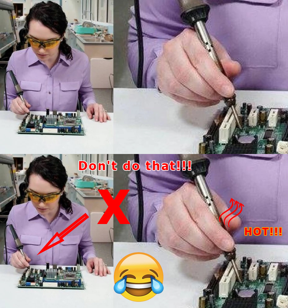
Safety
precautions
DO NOT!
ATTENTION!!!
When installing a color 3dMFD, there are 2 most important points.
1. You need to
configure the power supply to 5.5v.
The MFD operates at a voltage of
5.5v.
When you connect the power supply to the MFD you should make
sure that the output of the contacts is
5.5v, otherwise it
will damage the processor! Paragraph
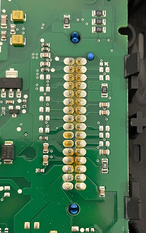
18 2. It is necessary to rinse all
soldering points. Install with extreme caution.
After soldering the wires, be sure to rinse the soldering
points with special flushing agents, or isopropyl alcohol.
During flushing, do not allow alcohol to get on the display
or under the display and its board!
При установке
цветного MFD есть
2 самых важных пункта:
1. Нужно настроить блок питания на 5.5в.
Модуль работает на напряжении
5.5в.
Кода вы подключаете блок питания к модулю,
вы должны убедиться в том, что на выходе контактов
напряжение
5.5в,
иначе это приведет к повреждению процессора!
2. Нужно промыть все места пайки.
Устанавливать предельно осторожно.
После пайки проводов обязательно
промыть места пайки специальными промывочными средствами или
изопропиловым спиртом.
Во время промывки не допускать попадания
спирта на дисплей или под дисплей и его плату!
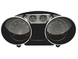
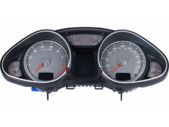
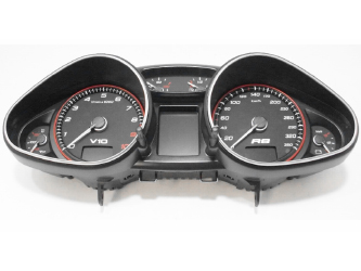
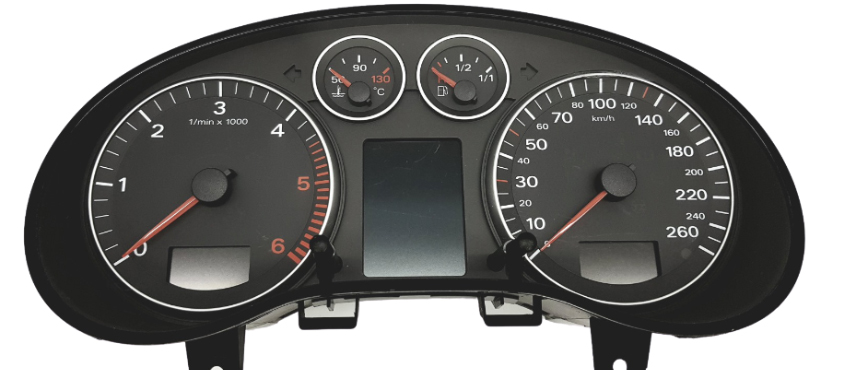
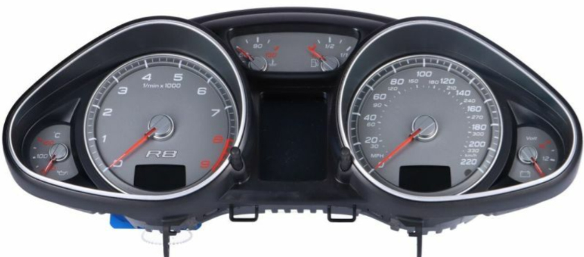
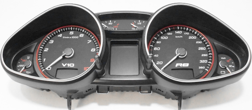
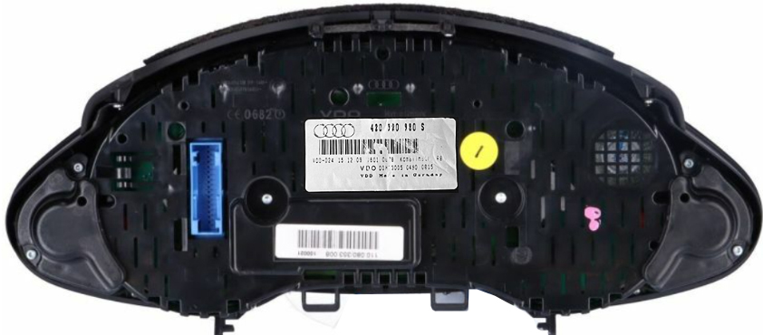
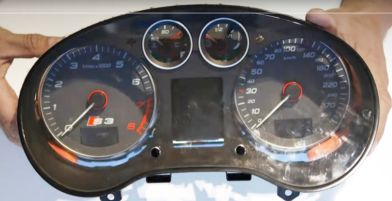
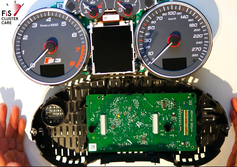
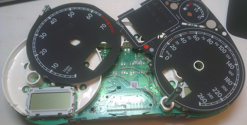
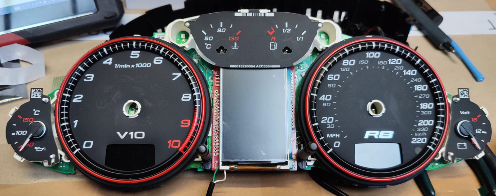
1. Disassemble the cluster.
1. Разбираем приборку
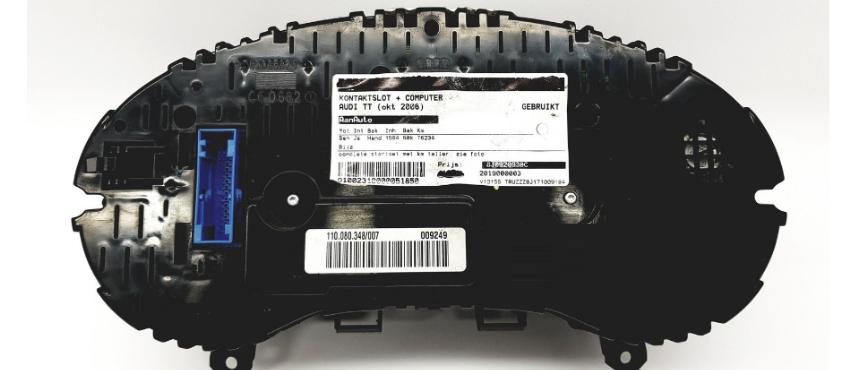
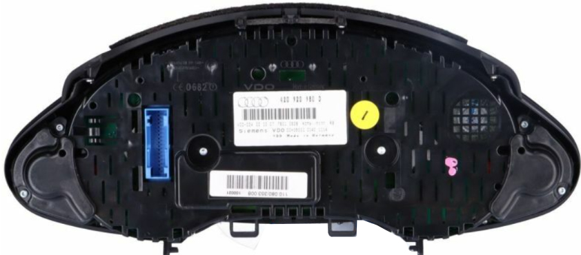
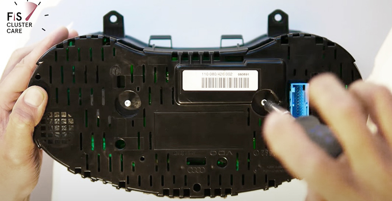
1.1 With a screwdriver torx T10, unscrew the two screws edges on the
rear of the instrument panel.
1.1.
Используйте отвертку ТОРКС Т10
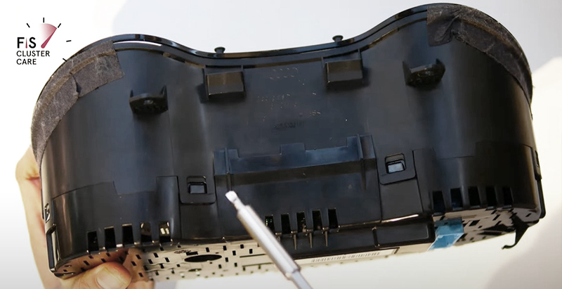
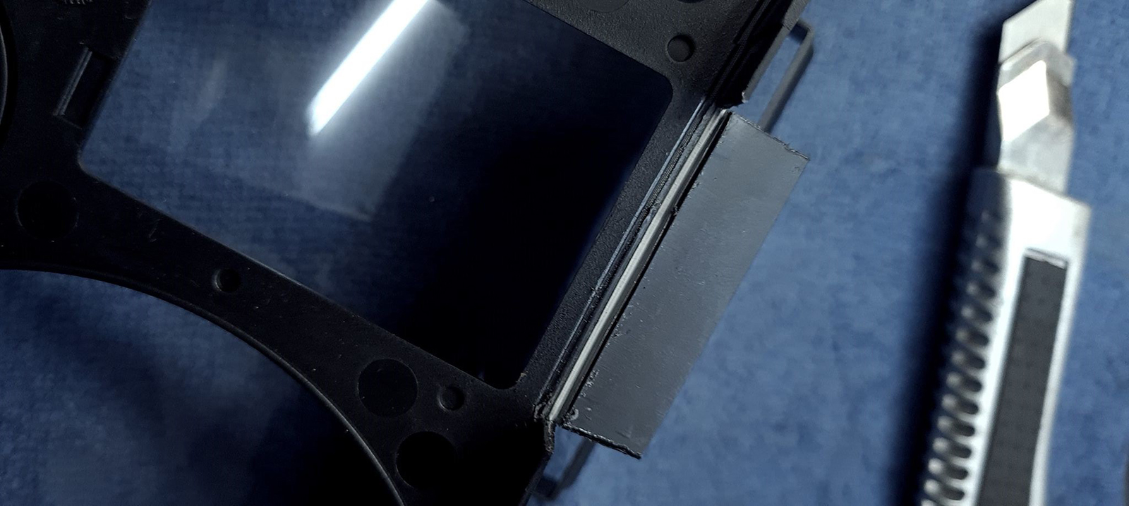
Bend all the latches and neatly remove the front of the case (with
glass).
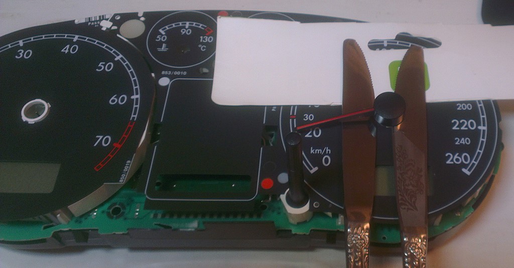
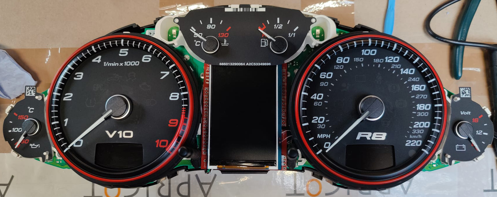
1.2 Remove the needles.
There are 2 ways to do it:
scroll counter-clockwise
and simultaneously pull it to yurself or
using using non sharp butter knives or spatula,
shoot the arrows from their shafts.Its
better to put paper between the knives and the base of the
device to avoid damaging it.
Pull the arrows up to yourself.
1.2 Удалите
стрелки. Сделать это можно двумя способами:
Крутите против часовой стрелки и
одновременно потяните
на себя.
Или используя неострые ножи для масла
или лопатку. Лучше положить бумагу между ножами и основанием устройства,
чтобы не повредить его. Вытяните стрелки к себе.
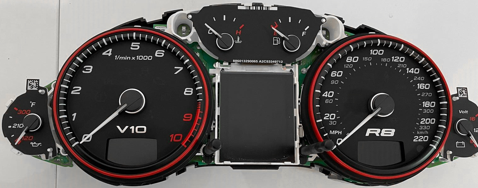
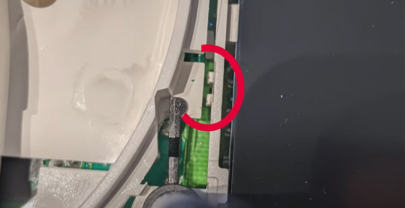
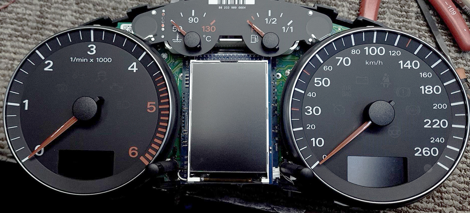
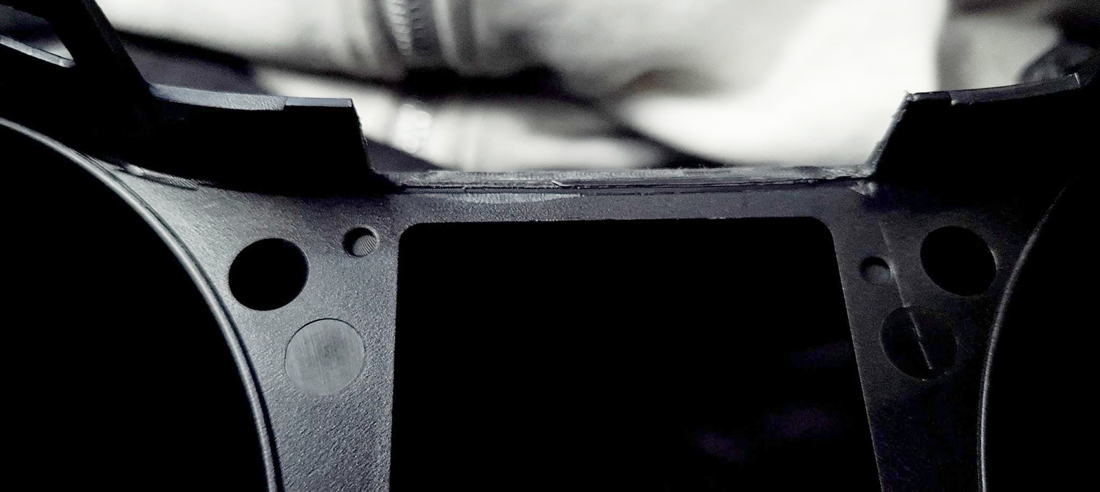
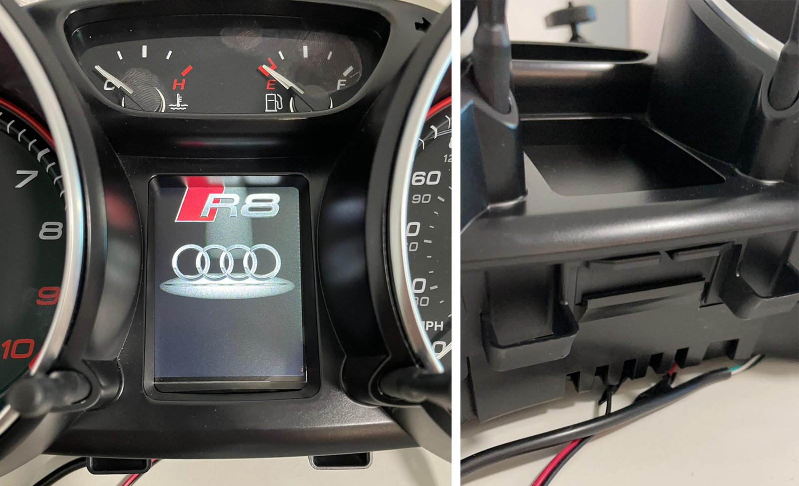
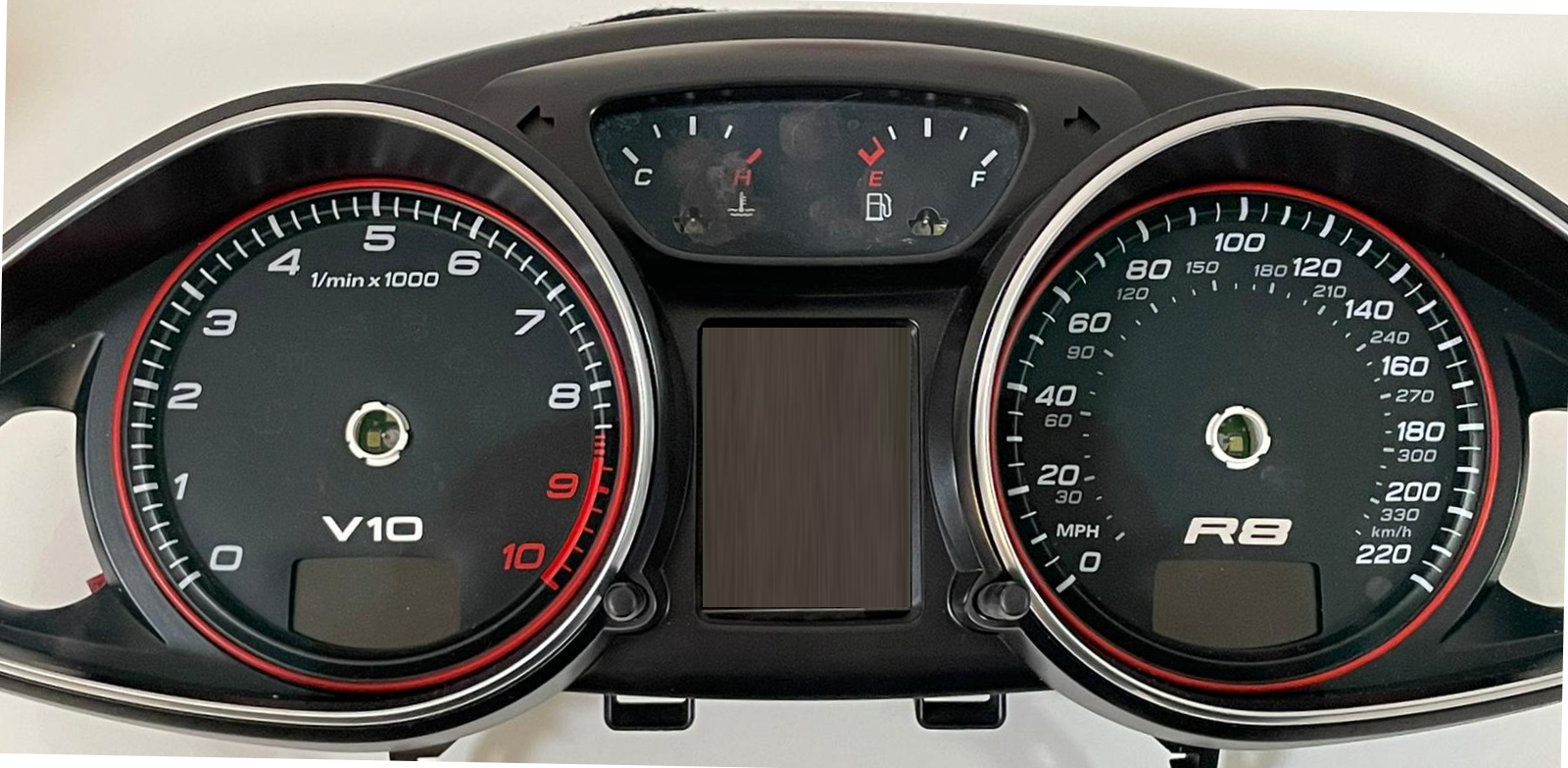
1.3.Then
remove the substrate. Удалите шкалы.
1.4.
Remove the OEM display, to do this you need to cut the white plastic
connection lines.. Удалите
оригинальный дисплей, для этого нужно перерезать линии
соединения белого пластика.
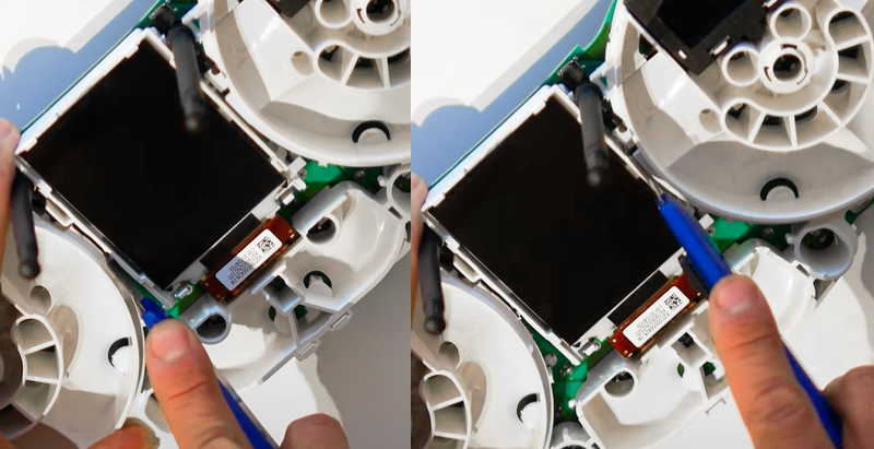
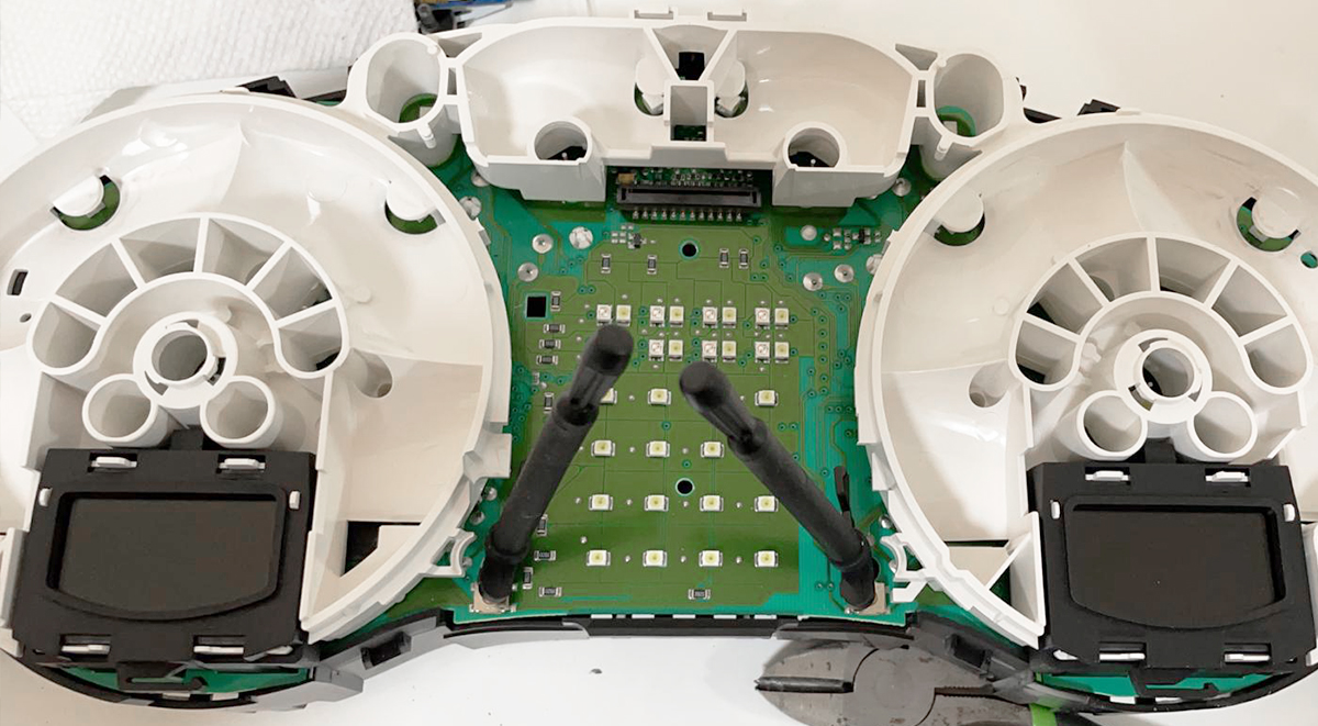
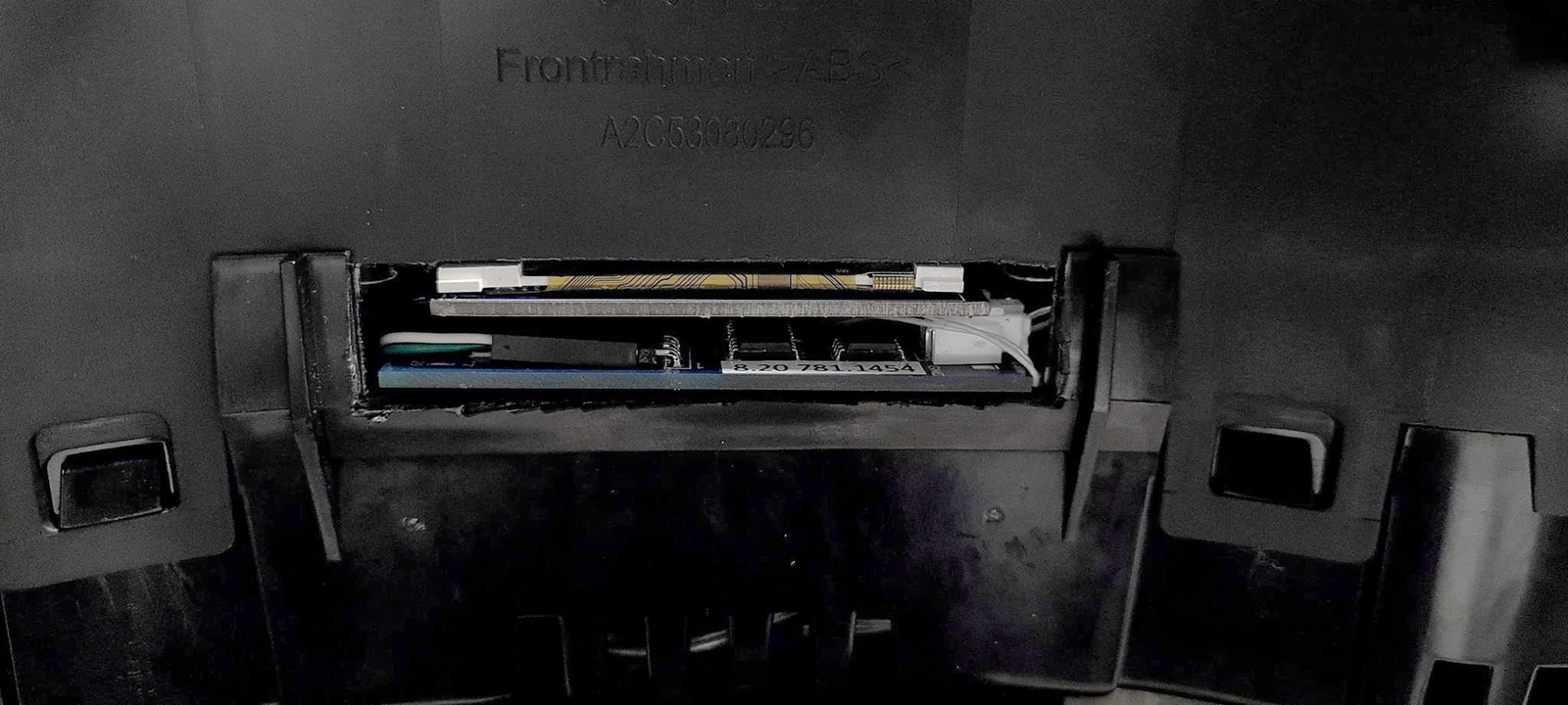
1.5.4. Remove the white display holder.
1.5.5. Снимаем белый
держатель дисплея.
На обратной стороне платы видны белые пластиковые защелки,
согните их пальцами и выньте белый пластик.
1.4.1.
Remove white plastic (noFIS)
Удалите белый пластик
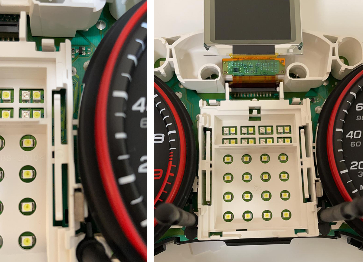
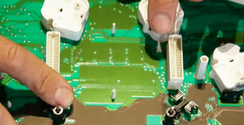
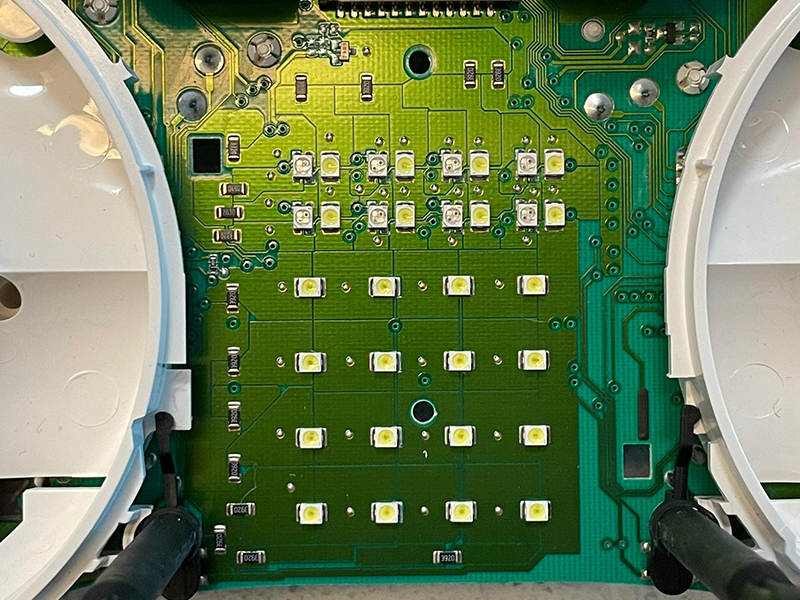
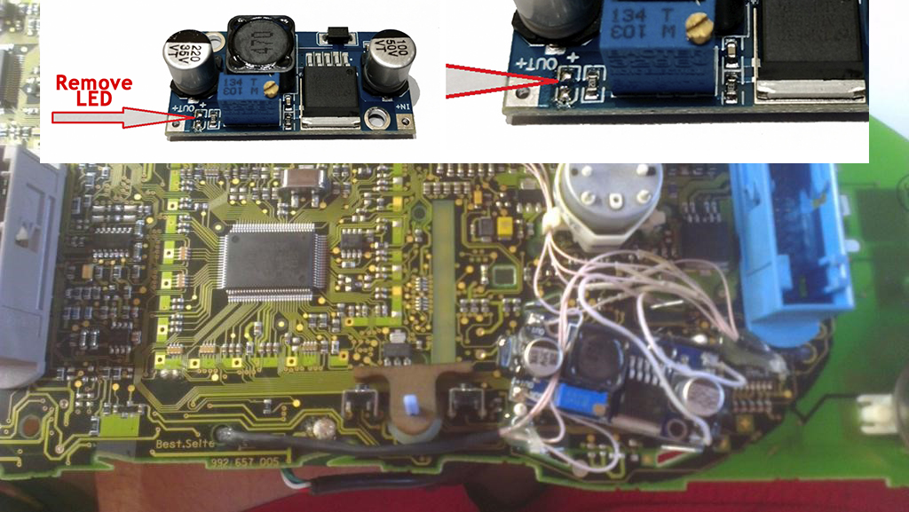
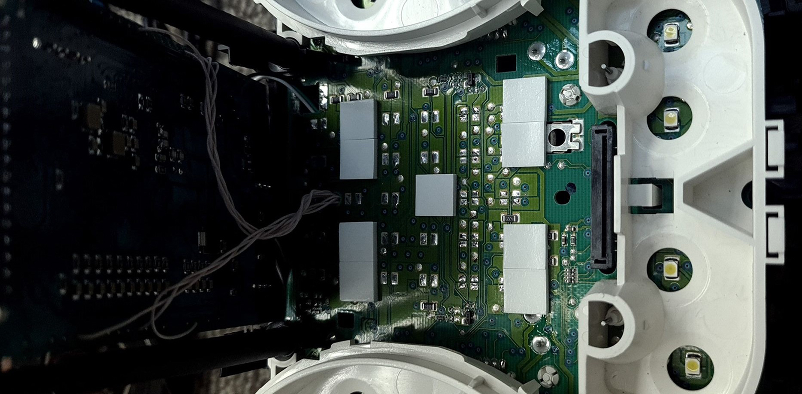
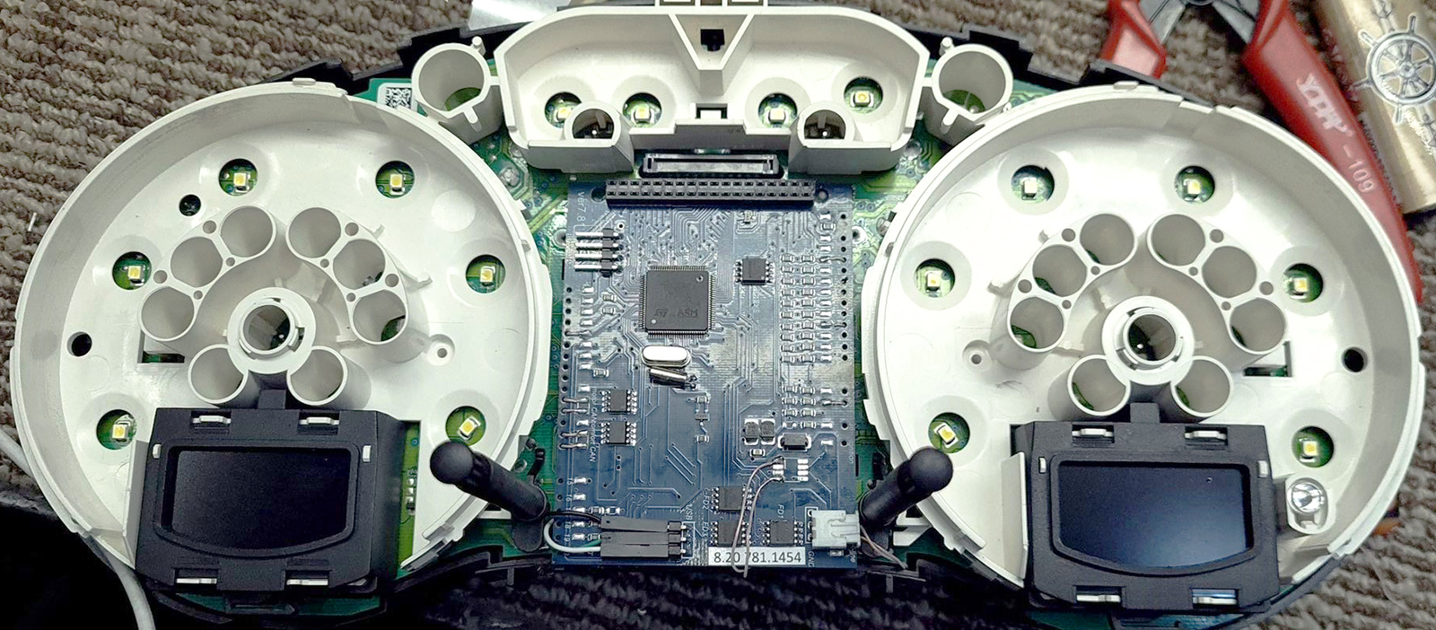
1.8. Next,
disconnect or remove the backlight LEDs of the original display. I
recommend removing only the resistors so that everything can be put
back if necessary.
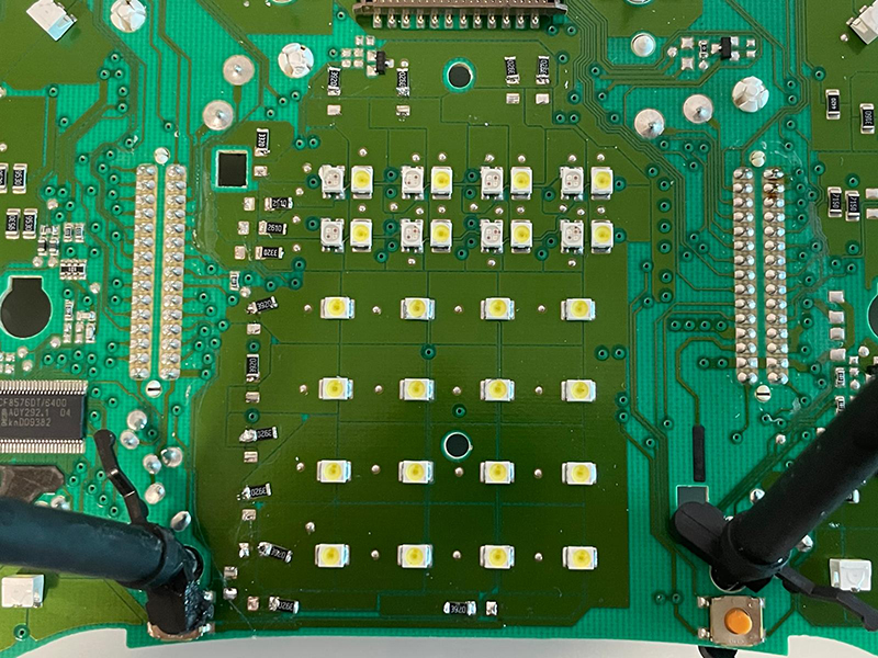
We make sure that
there are no jumpers made of tin.
After removing the LEDs, clean the board from tin residues and rinse
with alcohol.
1.8.
Дальше следует отключить или удалить светодиоды
подсветки оригинального дисплея. Я рекомендую удалить только
резисторы чтобы в случае необходимости все можно было вернуть назад.
Следим за тем,
чтобы не было перемычек из олова и.
После снятия светодиодов очистите плату от остатков олова и промойте
спиртом.
2. Installation / Установка
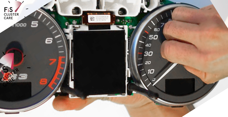
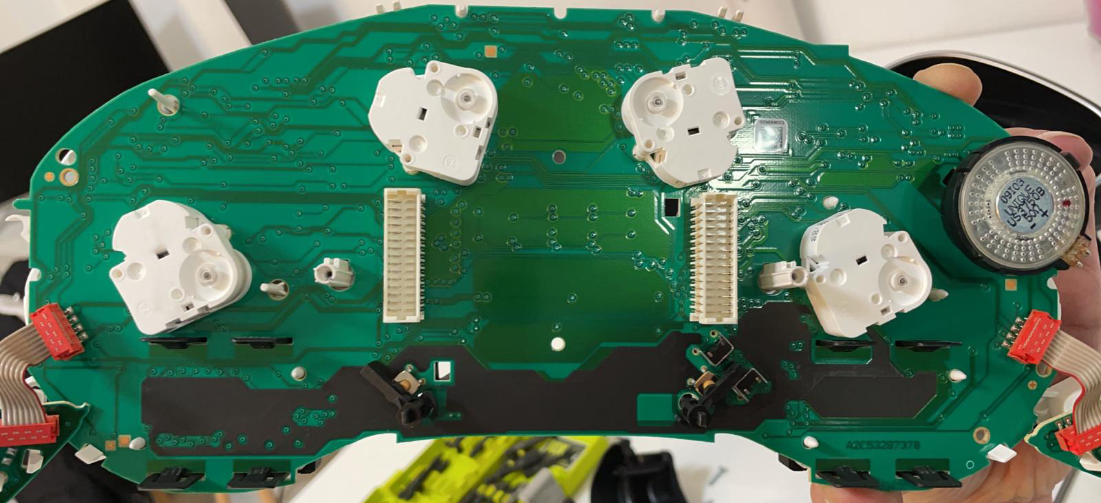
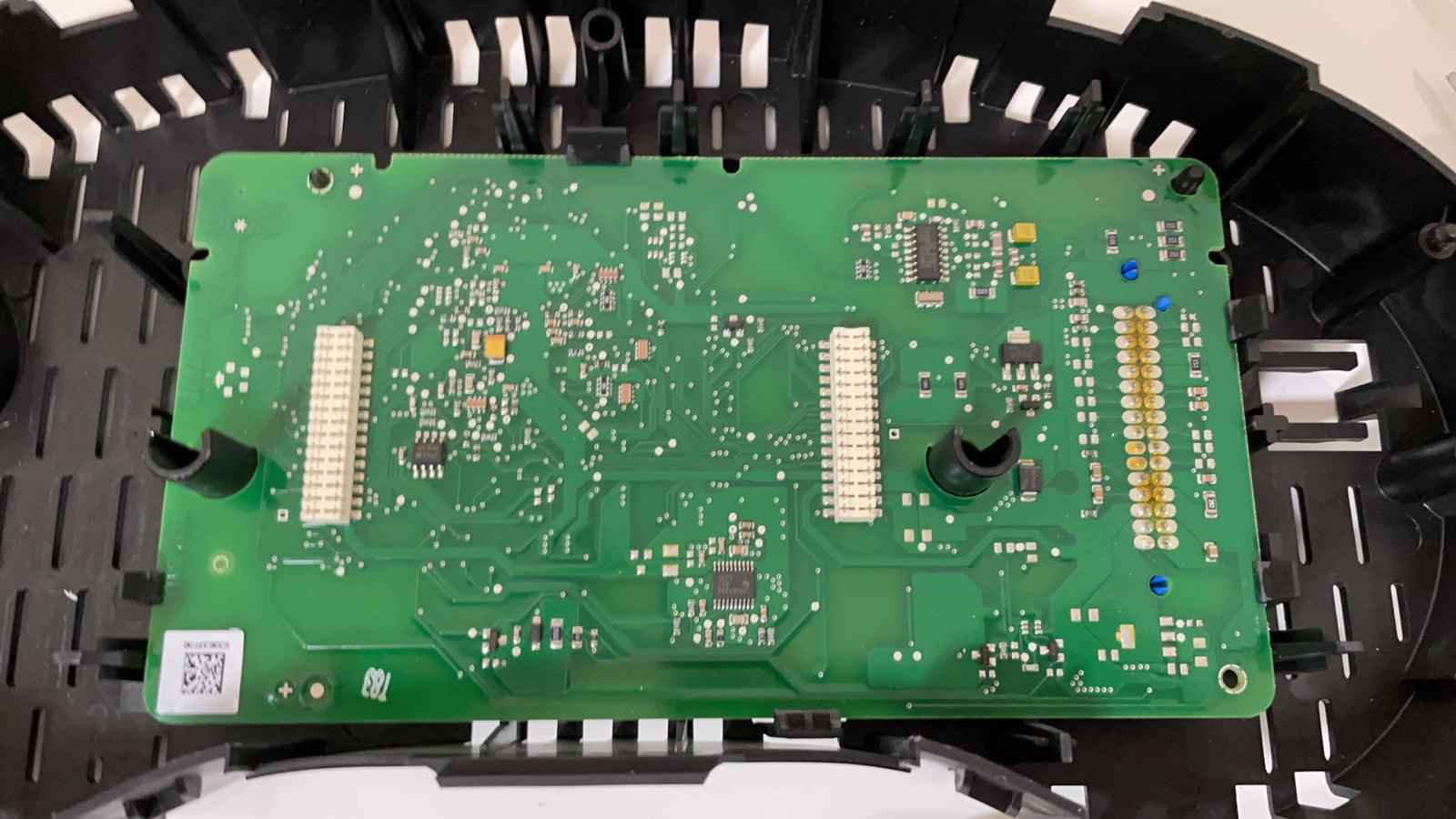
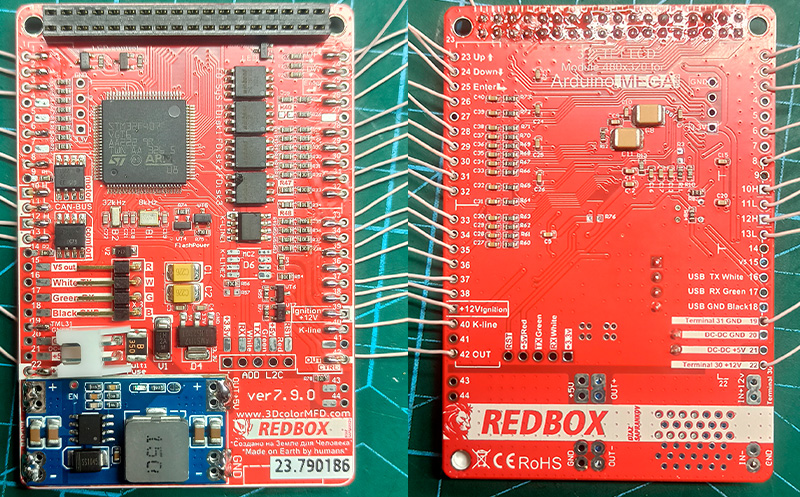
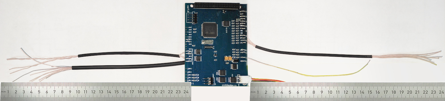
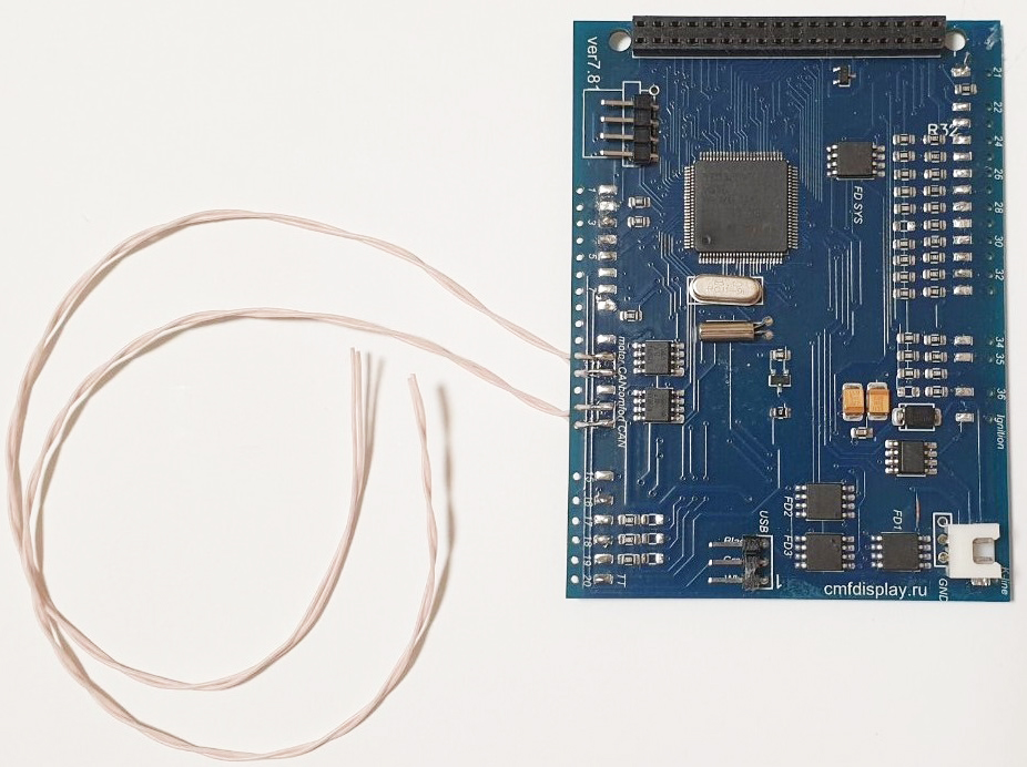
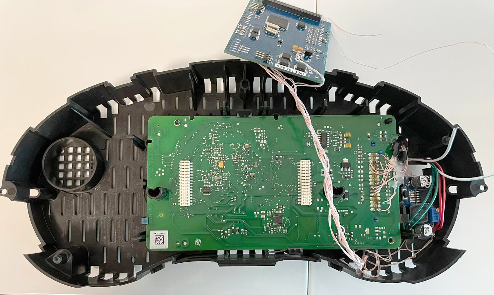
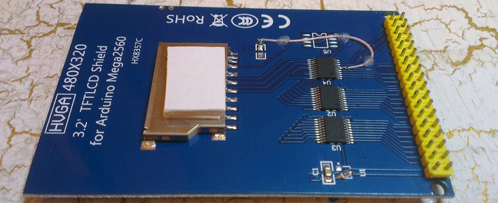
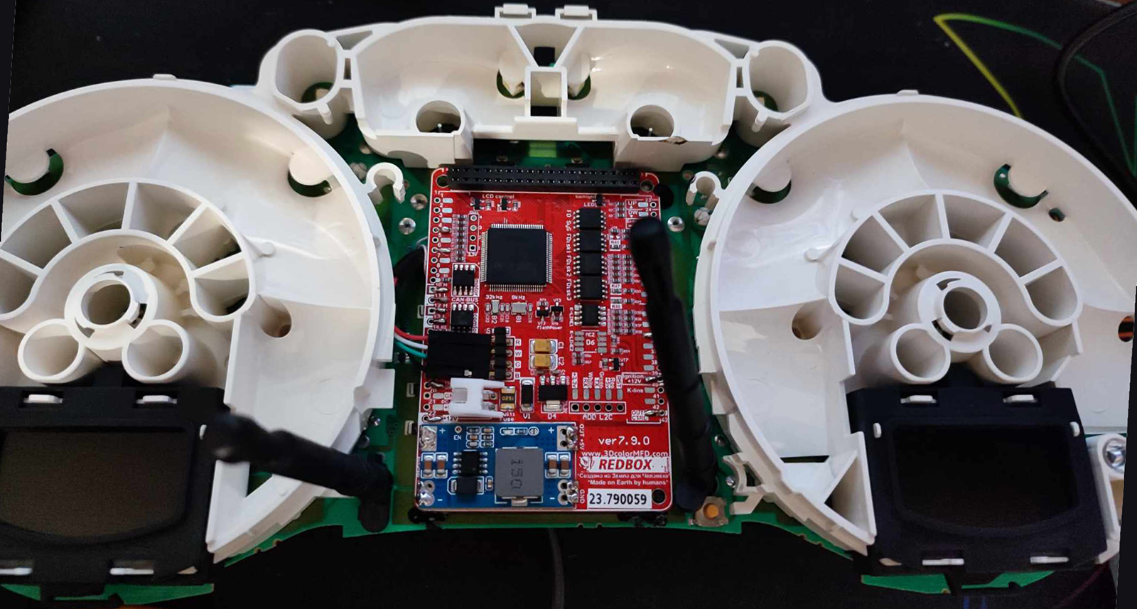
2.1.
Remove LCD board from motherboard and Stretch the wires from MFD
motherboard to the blue and green connectors through the holes in
the cluster`s board.
2.1. Снимите ЖК-дисплей и протяните провода
от материнской платы MFD к синему и зеленому разъемам через
отверстия в плате кластера.
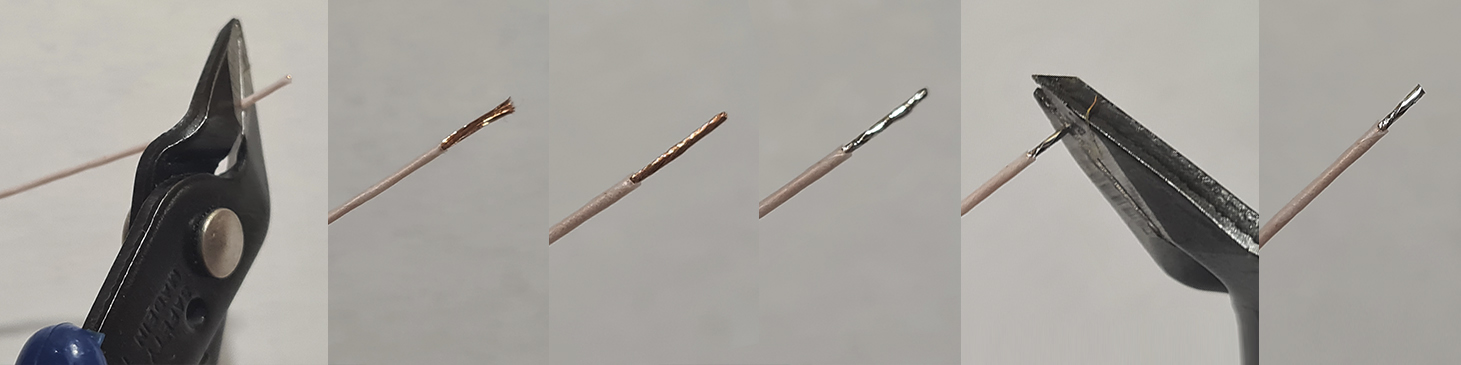
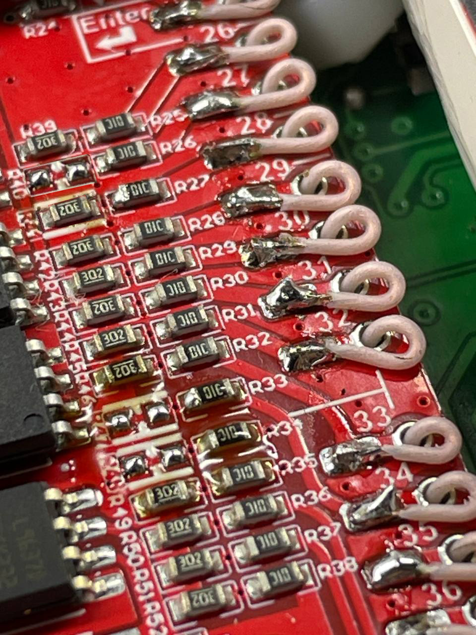
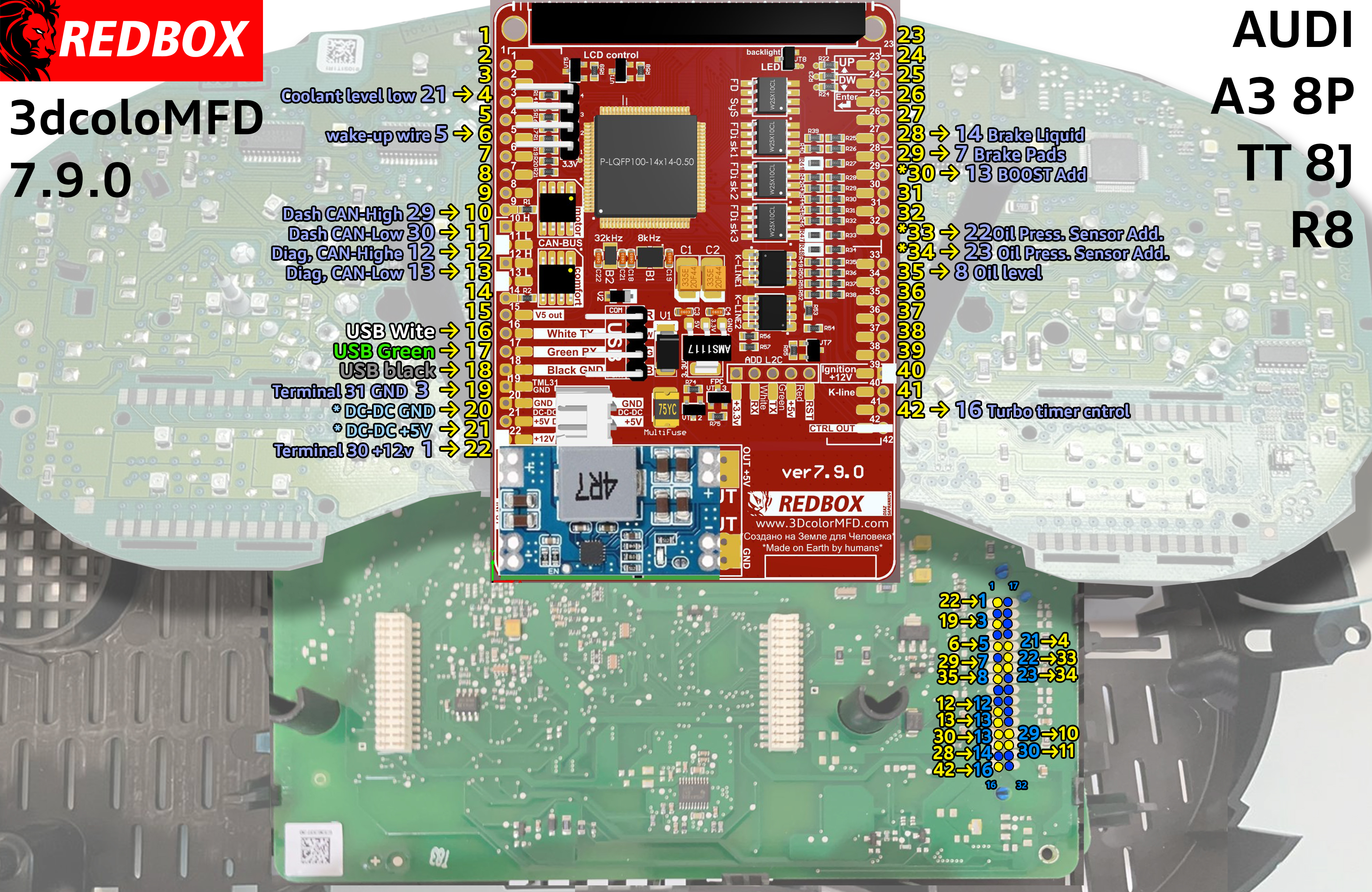
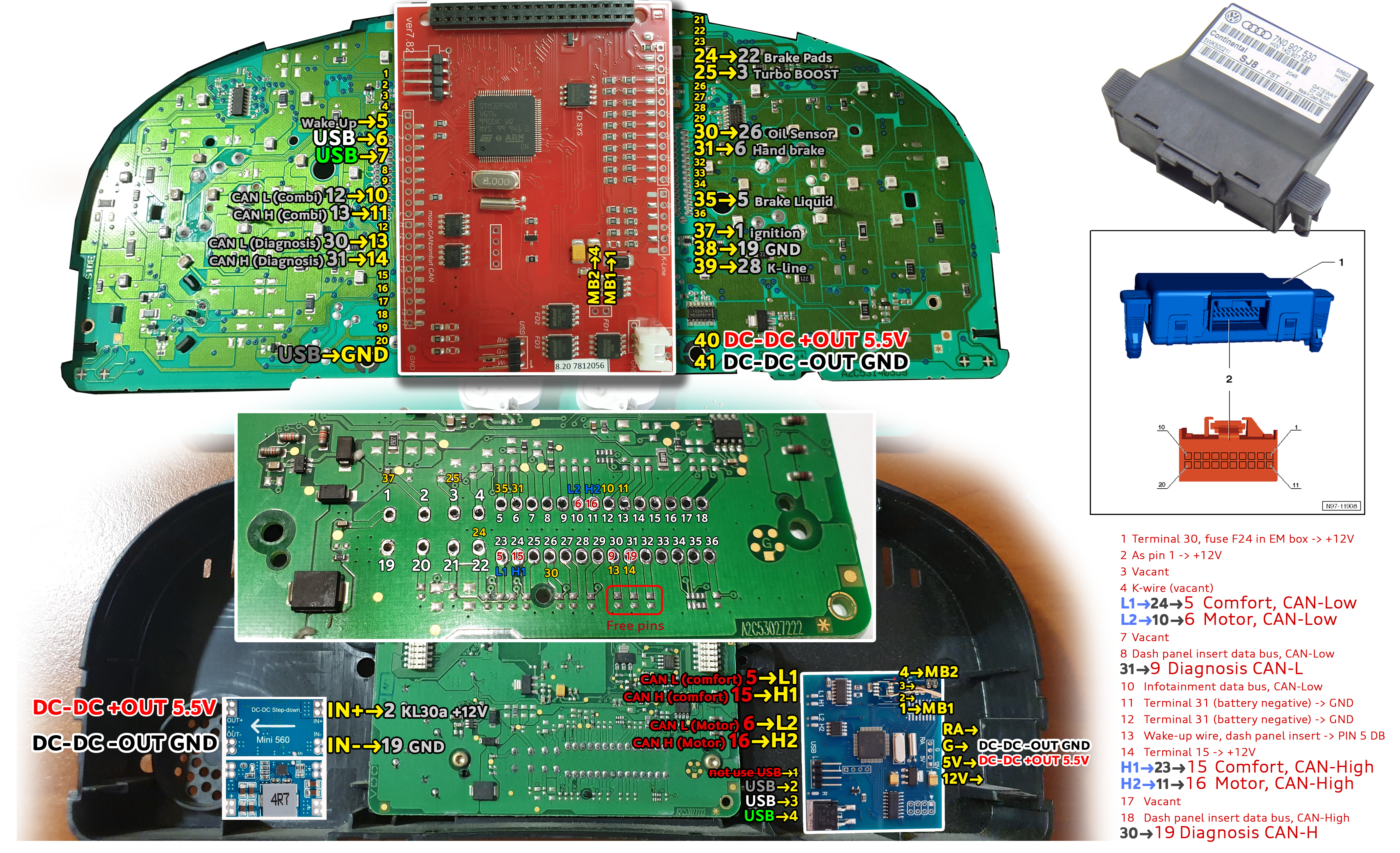
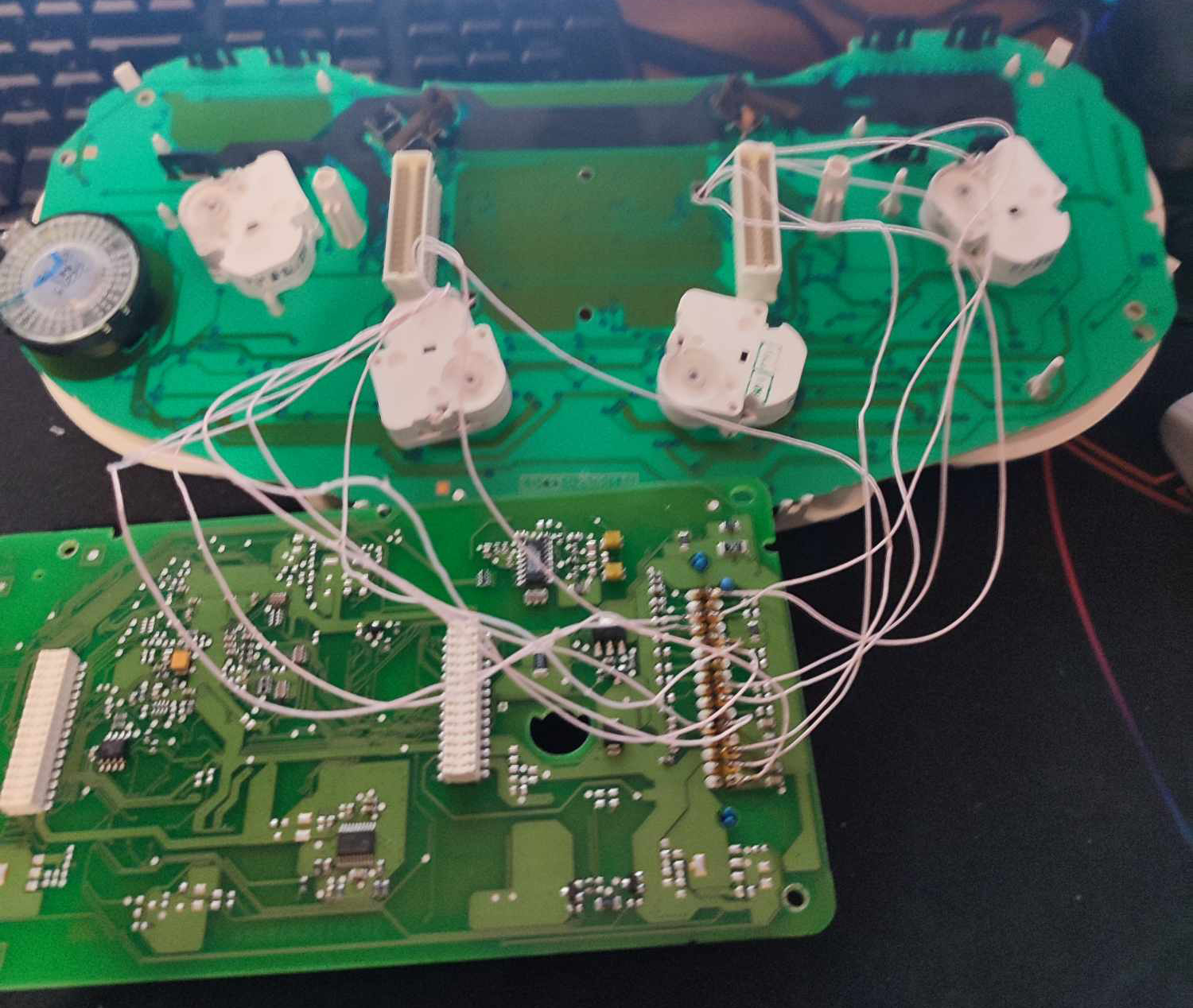
2.2 Start
to soldering wires according to the table. Wires should be cleaned
from Isolation, twisted and tin plated.
2.2 Приступаем к пайке проводов по таблице. Провода должны быть
очищены от изоляции, скручены и залужены.
photo by Александр Кiт
photo by Сергей
Прилуцкий
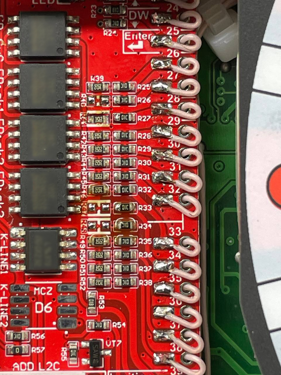
2.3
Take the multimeter, set it to Diode (Ring) mode.
Using multimeter and wiring diagram, find the wires
you need and solder them to the connector pins.
2.3 Используйте мультиметр,
установите его в режим диода (прозвонка)и схему подключения, найдите нужные провода и припаивайте
их
к контактам разъемов.
2.4 Обязательно скручивайте в спираль
провода, который вы будете подключать к CAN-шине.
3.1 Сluster does not have all the can-bus connections
what we need, so we need to lay the
missing can-bus wires from the can-bus gateway to the cluster.
you must run CAN-bus diagnostic wires.
3.1 Панель приборов не имеет все необходимые нам
can-bus соединения, поэтому нам
нужно проложить недостающие can-bus
провода от can-bus gateway
кпанели
приборов.
вы должны проложить провода CAN-bus
диагностики.
3.2 We have two ways to connect the
wires.
3.2
У нас есть два
варианта подключения проводов.
3.2.1. Way. Connect the wires in parallel
to the wires you already have in order to route them to the cluster.
1. Вариант. Подключить параллельно провода к уже имеющимся для тог,
чтобы проложить их к кластеру.
3.2.2. Way.
Use a special adapter.
2. Вариант. Использовать специальный переходник .
3.3. Lay the
wires in such a way that they do not interfere with the installation of
white Light diffuser.
3.3. Провода следует тянуть с тыльной
стороны или, как показано выше,так чтобы
при сборке приборки
провода не мешали.
Attention!
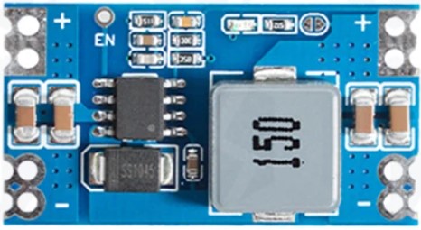
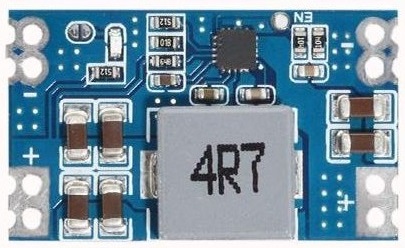
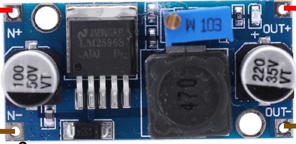
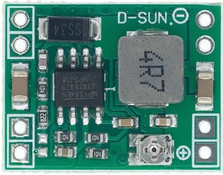
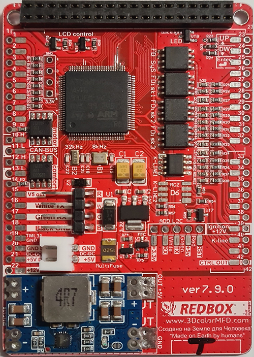
4. There are several types of DC-DC converters
ВНИМАНИЕ!
4.
Бывает несколько типов DC-DC
преобразователей
#1
#2
#3
#4
#1
This type of DC-DC converter is
already set to 5.2V
Этот тип DC-DC конвертер уже настроен
на 5.2В
#2 This type of DC-DC converter is
already set to 5.2V
Этот тип DC-DC конвертер уже настроен
на 5.2В
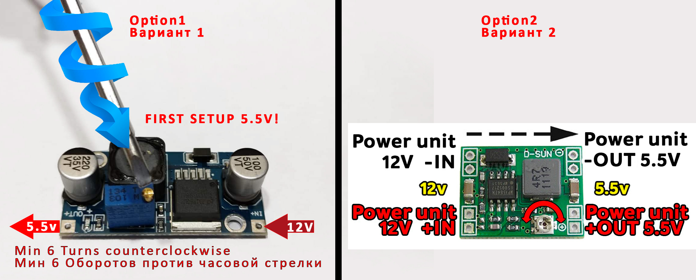
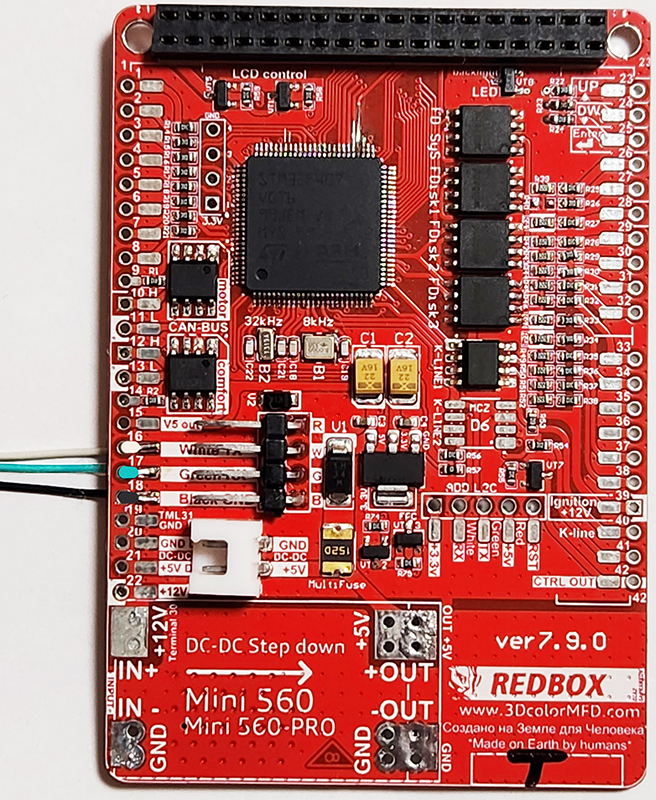
Attention!
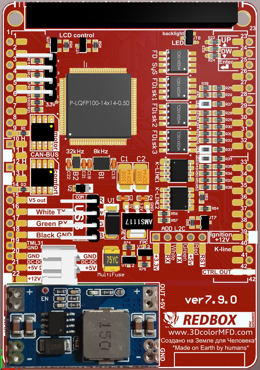
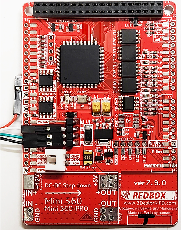
4.1. Before installing the power supply, you need to solder
the wires to it
contacts+IN-INand
+OUT-OUT,
then apply a current of 12V to +IN-IN,
andconnect
the+OUT-OUTwires
to the tester.
Now we need to adjust
the output current.Using
a small flat screwdriverslowly
rotate the special metal knob (figure 1 in the picture.) Clockwise
Arrow,
until, at us on the tester will not appear 5,5v in an output
voltage.
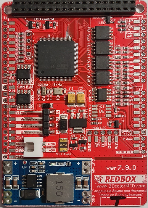
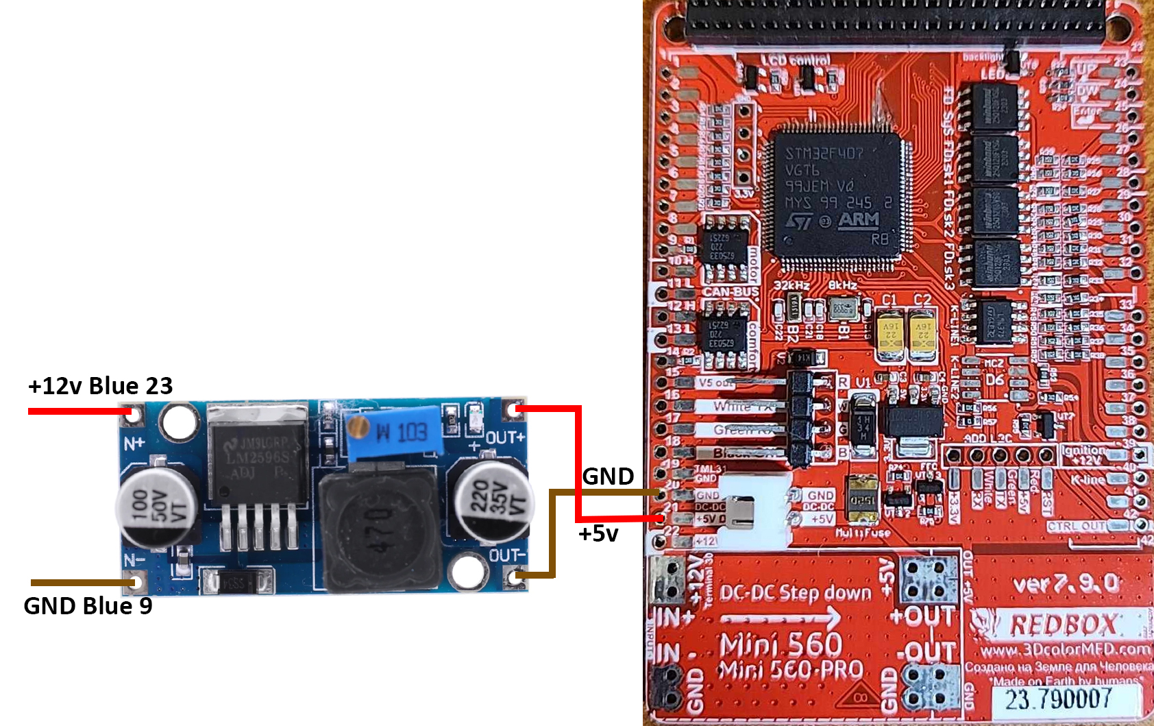
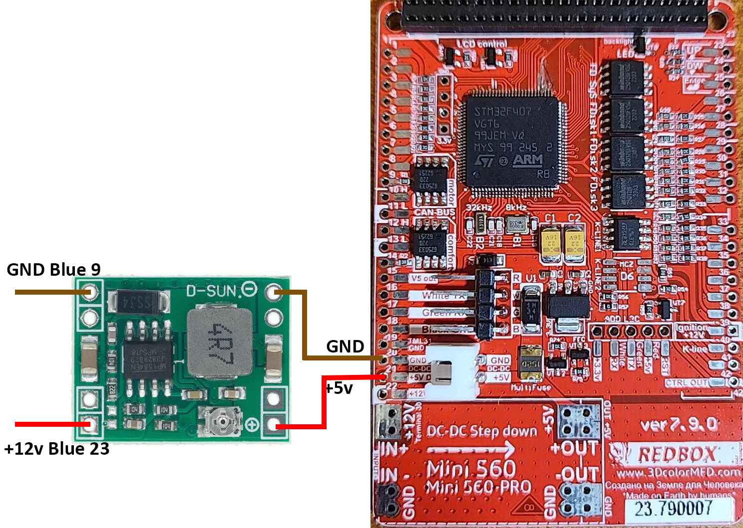
Next we
place the power supply unit on the back side, we bring to its
contacts the wires from the
blue connector.
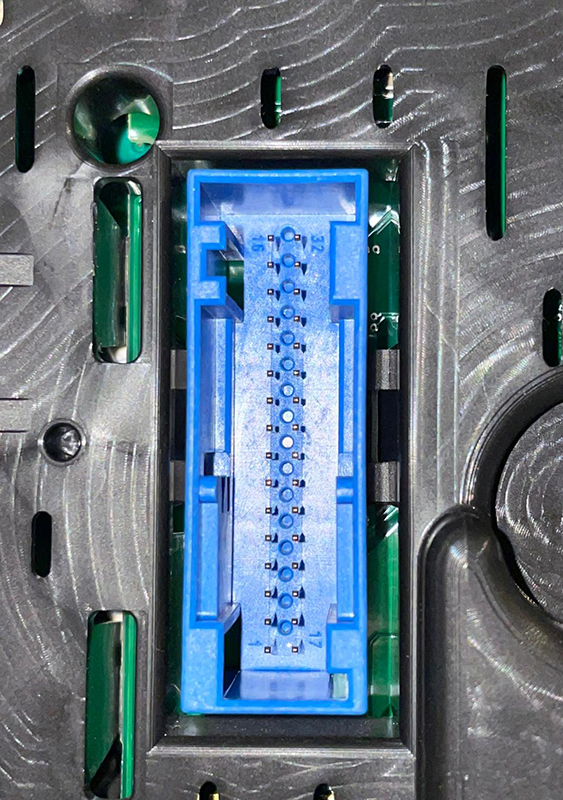
3
pin of blue
GND connector is
connected to the -INon
the power supply board. 1 pin of blue +12V connector
is connected to+INOn
the power supply board,
ВНИМАНИЕ!
4.1. Перед установкой блока питания
необходимо припаять к нему провода контакты + IN - IN и + OUT - OUT,
затем подайте ток 12 В на + IN - IN и подключите провода + OUT - OUT
к тестеру.
Теперь нам нужно настроить выходной ток. С помощью небольшой плоской
отвертки медленно поверните специальный винт (цифра 1 на рисунке) по
часовой стрелке много раз, до тех пор, пока, у нас на тестере не
появится +5,5v в выходном
напряжении. Далее размещаем блок питания с тыльной стороны, подводим
к его контактам провода от зеленого разъема.
3
контакт синего разъема -
GND
подключен к разъему -IN на плате блока
питания. 1контакт синего разъема
+12V
подключен к + IN на плате блока
питания,
4.2. Connect
+OUTConnects
to 21 pin MFD
-OUTConnects
to 20 pin MFD
Choose the place of
installation of the power supply so that during assembly it does not
interfere.Here
are the possible
4.2. Соедините
+ OUT Подключается к
21-контактному МФД
- OUT подключается к
20-контактному MFD
Место установки блока питания выбирайте так, чтобы при сборке
провода не мешали и не передавливались.
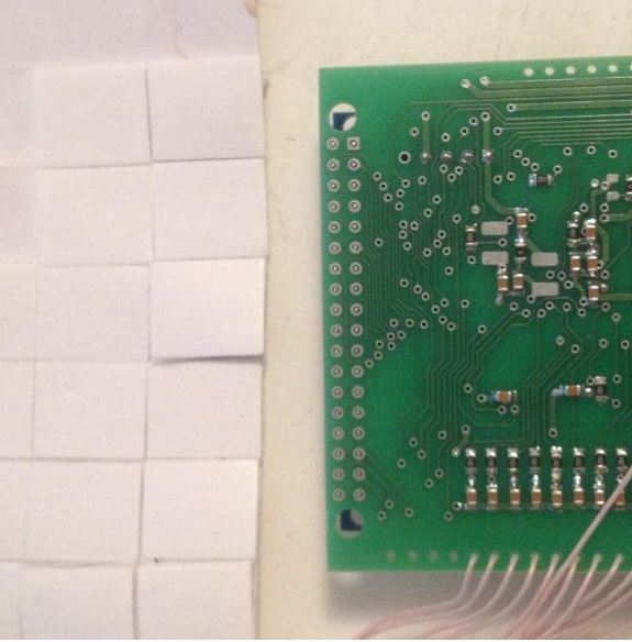
5. We take
double-sided adhesive tape on a foamy basis, cut the squares 1cmX1cm.
5. Берем двусторонний скотч и вырезаем квадраты 1см Х 1см.
5.1. We collect these
squares in 3 floors.
5.1.
Собираем
скотч в 3 слоя.
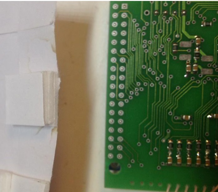
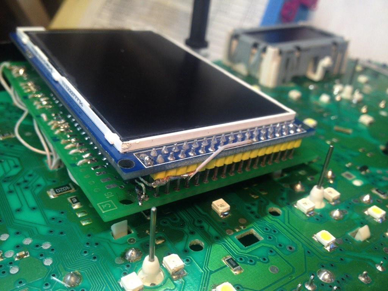
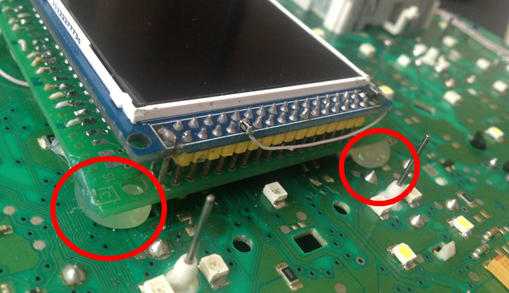
5.2. And we place it on the
3dMFD board, the height of the adhesive tape should be enough so
that the 3dMFD board does not touch the cluster board.
5.2. И
размещаем на плате 3dMFD, высоты скотча
должно быть достаточно, чтобы плата 3dMFD
не касалась платы приборки.
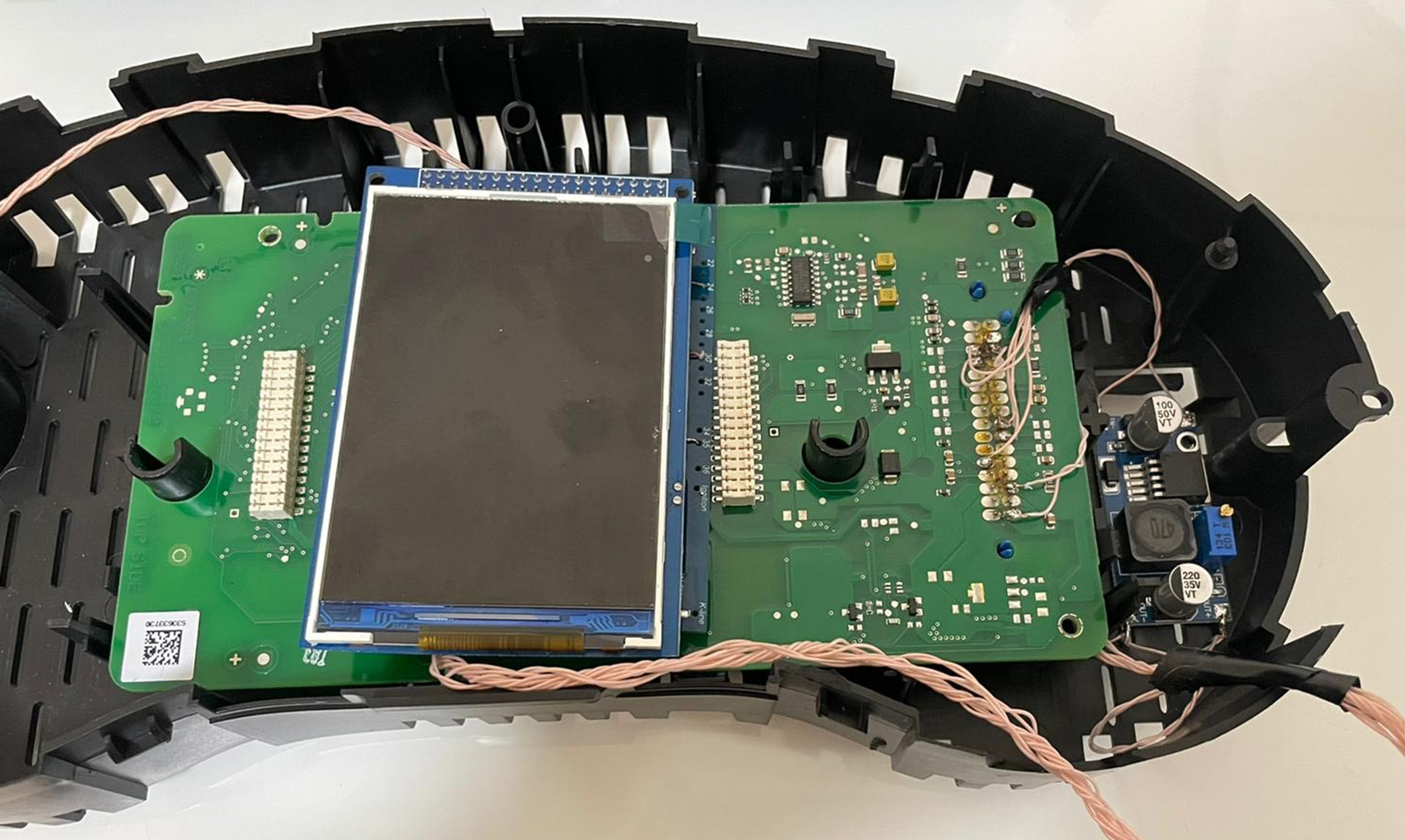
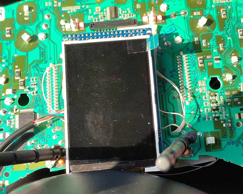
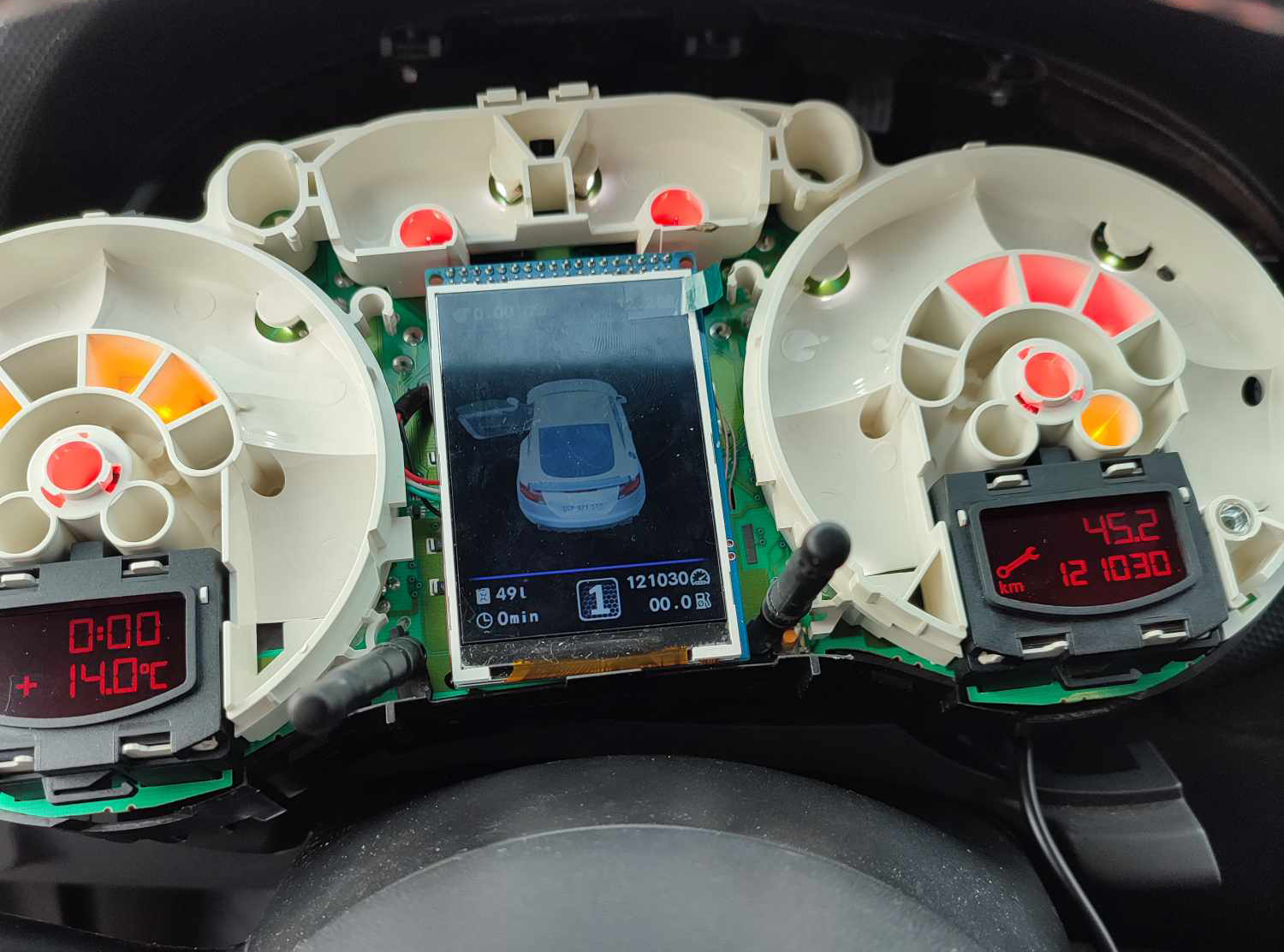
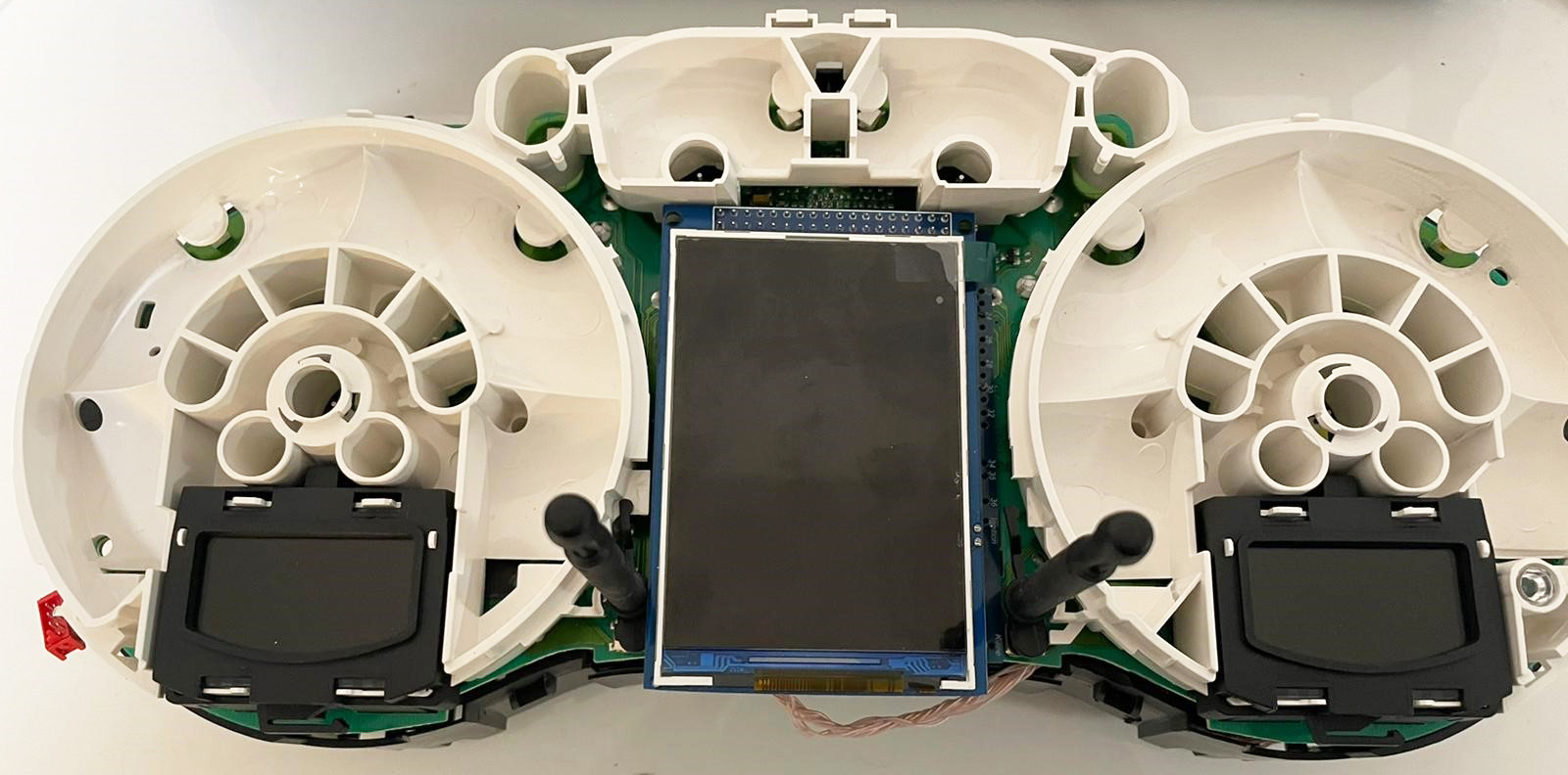
5.3. Place the module so that it is placed in the window of
the device
5.3. Разместите модуль так, чтобы он находился в оконе маски
приборки.
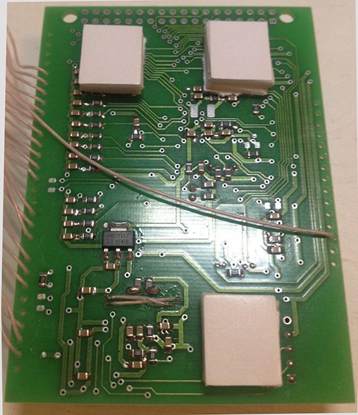
5.4.
For greater reliability, when the module is already installed on the
board,
and you calibrated it in the window so
that there were no distortions, it is better to fix it.
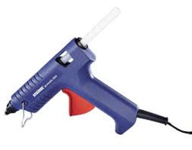
Its hot glue along the edges of the module.
5.4. Для большей надежности, когда модуль
уже установлен на плате, а вы откалибровали дисплей так чтобы не
было перекосов, вы можете зафиксирвать палту
3dMFD горячим клем по краям модуля. не нужно заливать
полностью всю плату в 2 -3 точках будет достаточно.
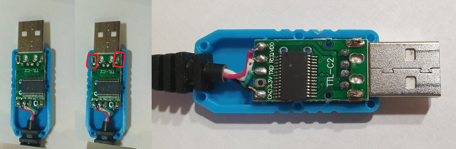
6.
BETTER
USB connection option, you must solder the wires to the board.
6. Предпочтительный
вариант подключения
USB, вы должны припаять провода к плате.
6.1.Acceptable
USB connection option, you can use the connector.
6.1.
Допустимый вариант подключения
USB, вы можете использовать разъем для подключения.
6.2.
OpenUSB
And solder
the metal ears marked in red.
6.2. Откройте
USB и припаивайте металлические уши отмеченные красным
7.
Before installing the display, you need to glue double-sided
adhesive tape into three layers on the back of the display to lock
the display.
Attention, you do not need to attach
modules to the board!
It is enough simply to remove an additional support from a
double-sided adhesive tape without removing the protective layer
from the side of the module board.
7. Перед
установкой дисплея нужно приклеить двухсторонний скотч, для того
чтобы создать дополнительную опору Внимание!
Приклеивать дисплей к плате 3dMFD не
нужно!
Достаточно просто снять дополнительную опору с двустороннего скотча,
без снятия защитного слоя со стороны платы 3dMFD.
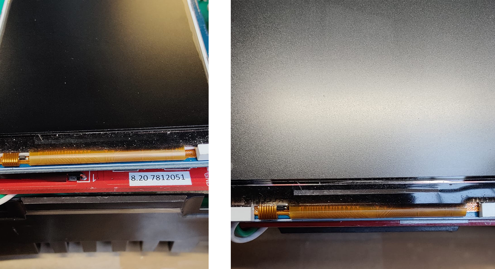
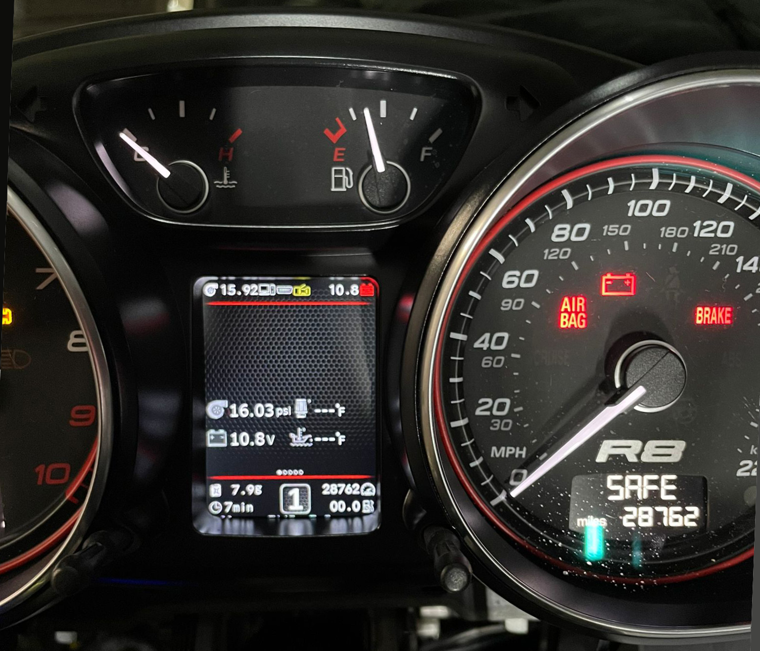
8. After you
solder the wires and set the display to its place, you need to
test the 3dMFD
performance in the car to make sure everything is properly installed
and working well.
8. После того, как вы припаяли
все провода и установите дисплей на место, dам
необходимо протестировать работу 3dMFD в
автомобиле, чтобы убедиться, что все правильно установлено и
работает нормально.
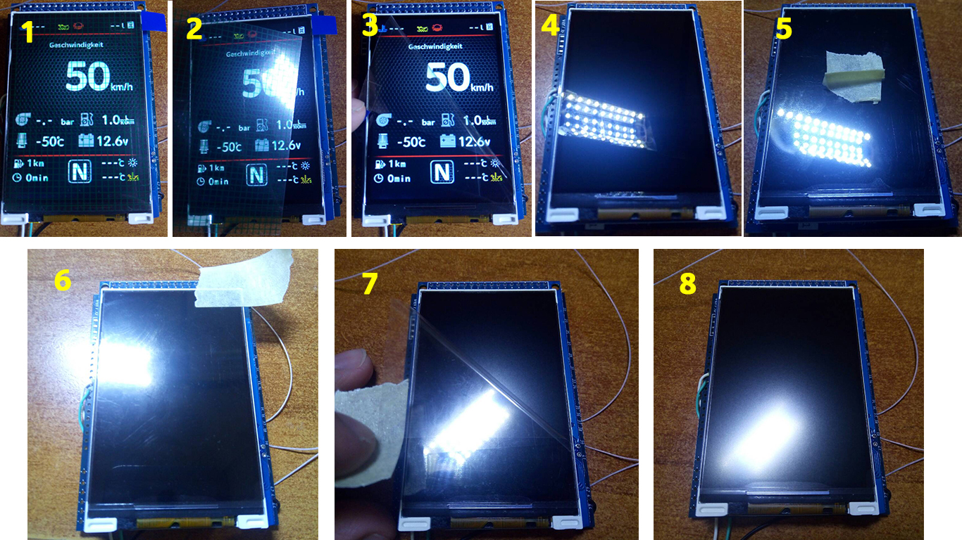
9. Next, you
need to glue the matte protective film so that the display does not
glare in the sun.
Unfortunately, the film may not always be included, but it is easy
to find on Marketplace, you can use a polyurethane matte screen
protector for any smartphone just cut out with scissors to the right
size.
9. Далее нужно приклеить матовую
защитную пленку, чтобы дисплей не бликовал на солнце. К
сожалению пленка не всегда может быть в
комплект, но ее легко найти на маркетплейсах, вы можете использовать
полиуретановую матовую защитную пленку для экрана любого смартфона
просто вырезав ножницами нужный размер.
Attention!
BCarefully install the cluster case!
Otherwise, you may damage the display!
Внимание!
Аккуратно устанавливайте маску приборки!
В противном случае вы можете повредить дисплей!
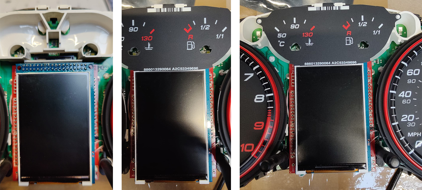
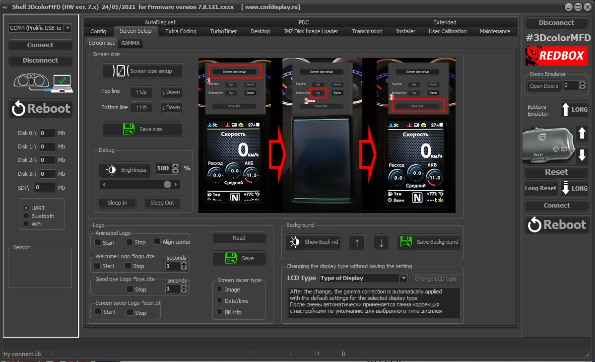
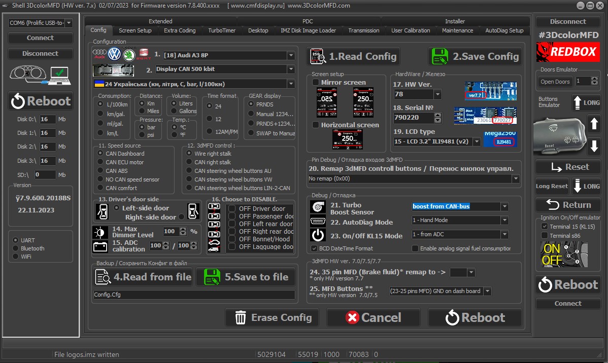
10. Using the Shell -> Screen Size program,
adjust the display frames according to the window in the tidy scale.
10.
С помощью программы Shell -> Screen Size
настройте рамки дисплея по окну в шкале приборки.
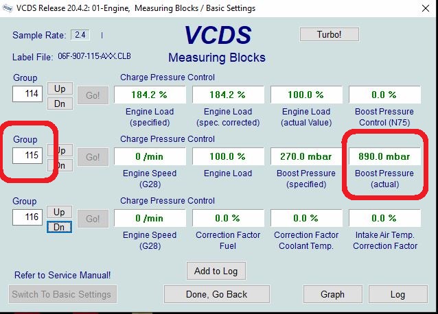
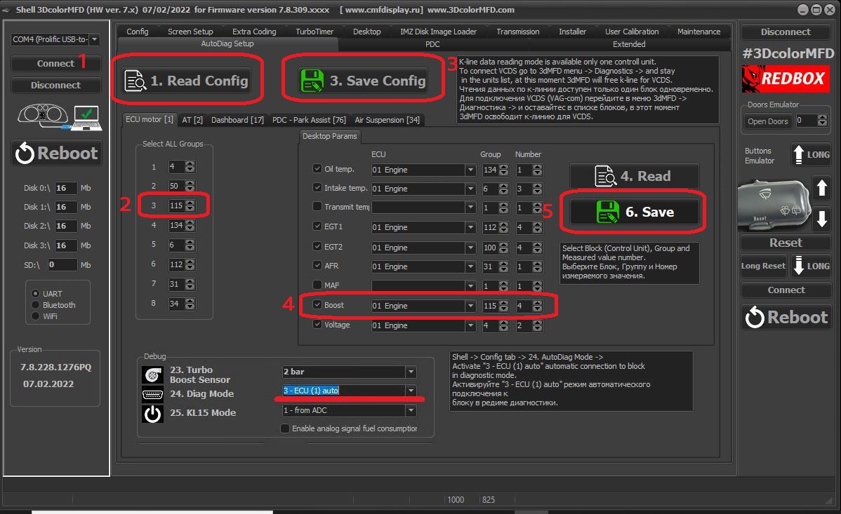
11. After you have laid the
signal wire from the engine ECU to the cluster,
make a setting in the Shell program so that 3dMFD displays the turbo
boost pressure. You need to set the boost
from CAN, you can do this experimentally by selecting it
from the list in the Shell program.
11.
После того как вы проложили сигнальный провод от ECU
двигателя к приборке
сделайте настройку в
программе Shell, для того чтобы 3dMFD
отображал давление наддува турбины.
Вы должны установить
boost from CAN, вы можете сделать
это опытным путем подбирая его по списку в Шелл программе.
12. Assembly.
And then we collecteverythingin
the reverse order withoutforgetting
to calibrate the
needleswith the help of the WAG-com.
12.
СБОРКА.
Собирайте все в обратном порядке, не забывая калибровать иглы с
помощью программы VAG-com.
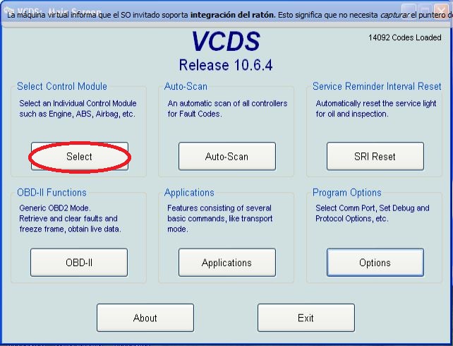
12.1.
To
do this, connect the device to the machine without installing the
glass, connect the VAG-com.
12.1 Для этого
установите приборку в автомобиль
(без стекла) и подключите его VAG-com.
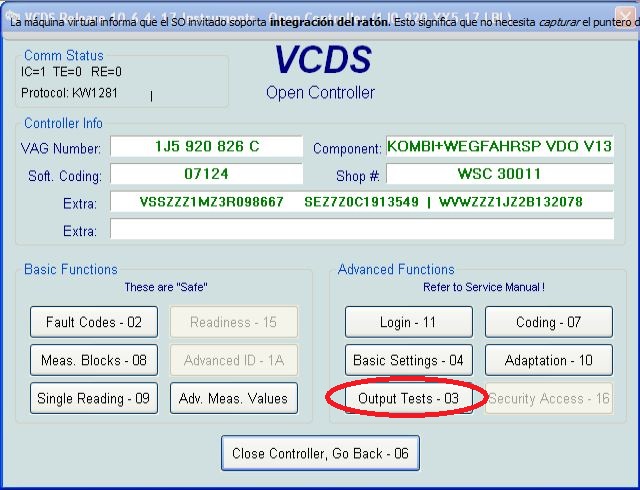
12.2.Go
into the 17-unit dash panel
12.2Зайти
в 17-блок панель приборов
12.3.Select
test performers.
12.3.Выбрать
"Тест исполнителей".
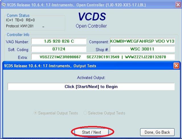
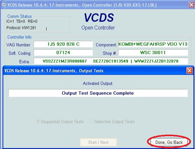
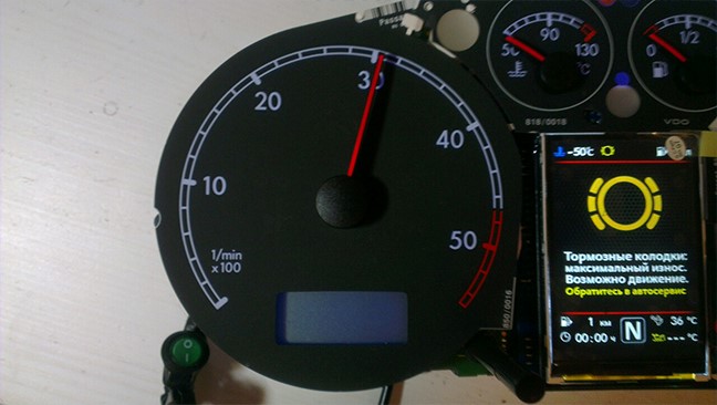
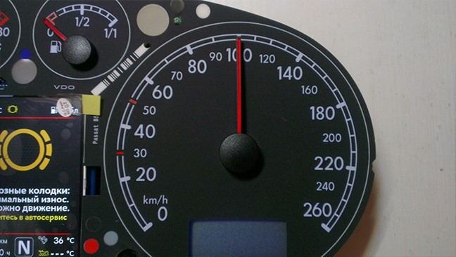
12.4.Choosing
in turn a tachometer, temperature and the rest, the arrows in turn
will be
Do a turn on
the whole scale, and then freeze on:
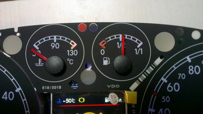
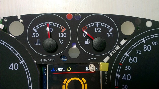
12.4 Сделайте тест стрелок.
Выборайте по очереди: тахометр, температура охлаждающей
жидкости, уровень топлива и скорость Стрелки
пройдут по вей шкале, а затем
остановятся
в контрольных точках. Запомните или сделайте фотографию разницы в
показания. Нажмите
«Готово» и выйдите из блока. Выключите зажигание, выньте
ключ и установите иглы в правильное положение, повернув их
назад против часовой стрелки.
12.5.Tachometer - 3
thousand revolutions
12.5.Тахометр - на 3 тыс. оборотов
12.6.Pace.Coolant
- middle
12.6.
Спидометр - на 100
км/ч
12.7. Fuel
level - middle
12.7. Уровень температуры ОЖ -
по средине
12.8.Speedometer
- at 100 km / h
12.8. Уровень топлива -
по средине
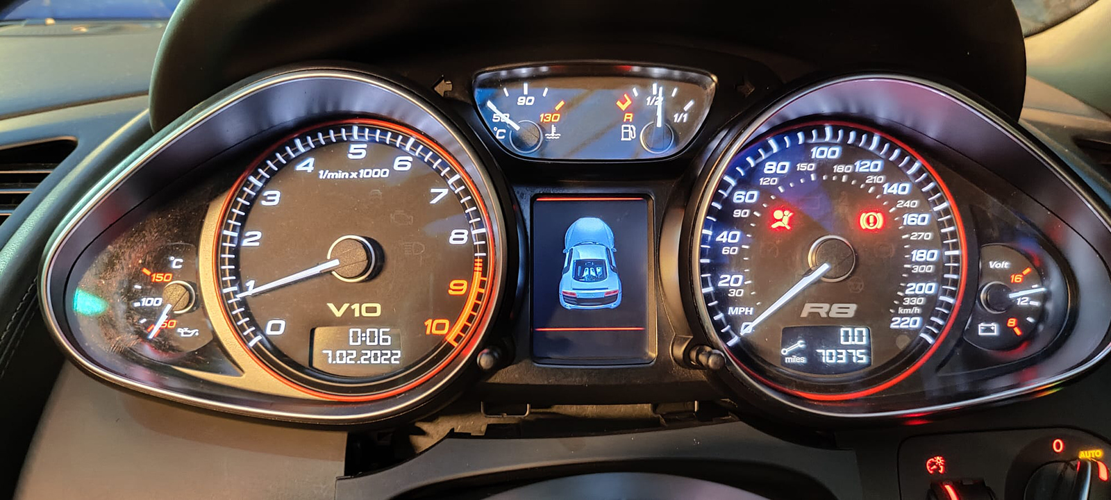
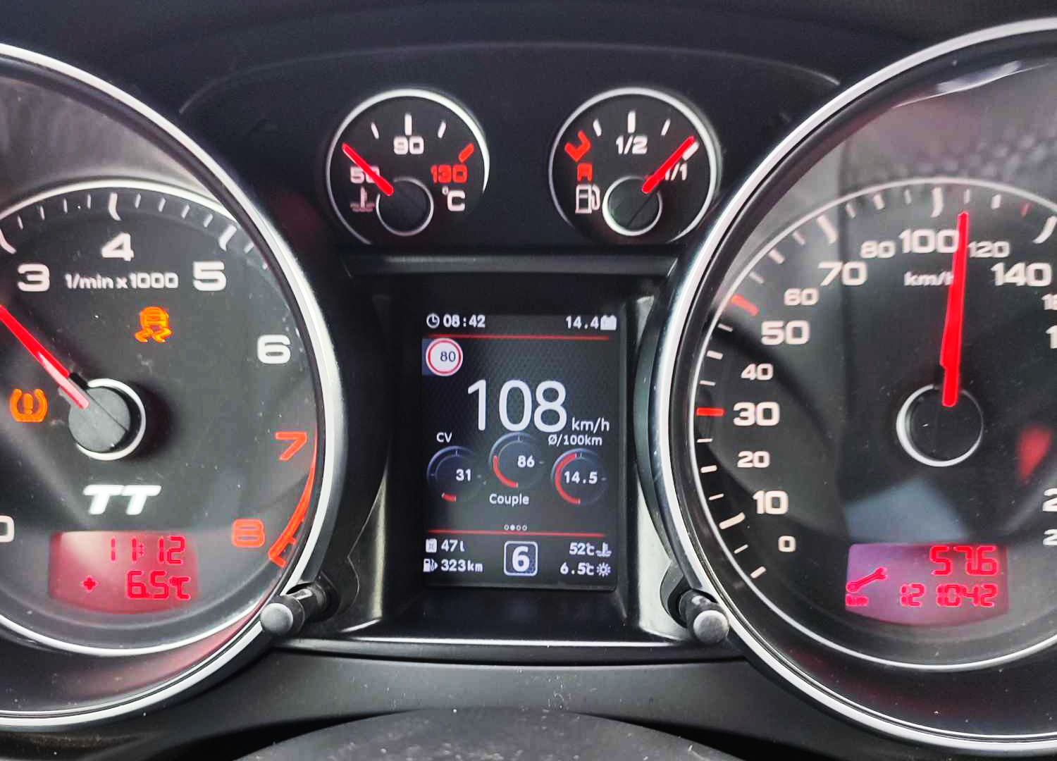
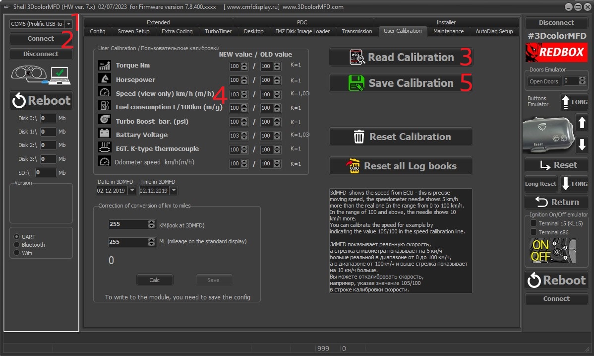
3dMFD shows the speed from EСU - this is precise moving speed, the
speedometer needle shows 5km/h more than the real one In the
range from 0 to 100km/h.
In the range of 100km/h and above, the needle shows 10km/h more.
You can calibrate the speed for example by indicating the value
105/100 in the speed calibration line.
3dMFD показывает реальную скорость, а стрелка спидометра
показывает на 5км/ч больше реальной в диапазоне от 0 до 100
км/ч, а в диапазоне от 100км/ч и выше стрелка показывает на 10км/ч
больше.
Вы можете откалибровать скорость, например, указав значение 105/100
в строке калибровки скорости.
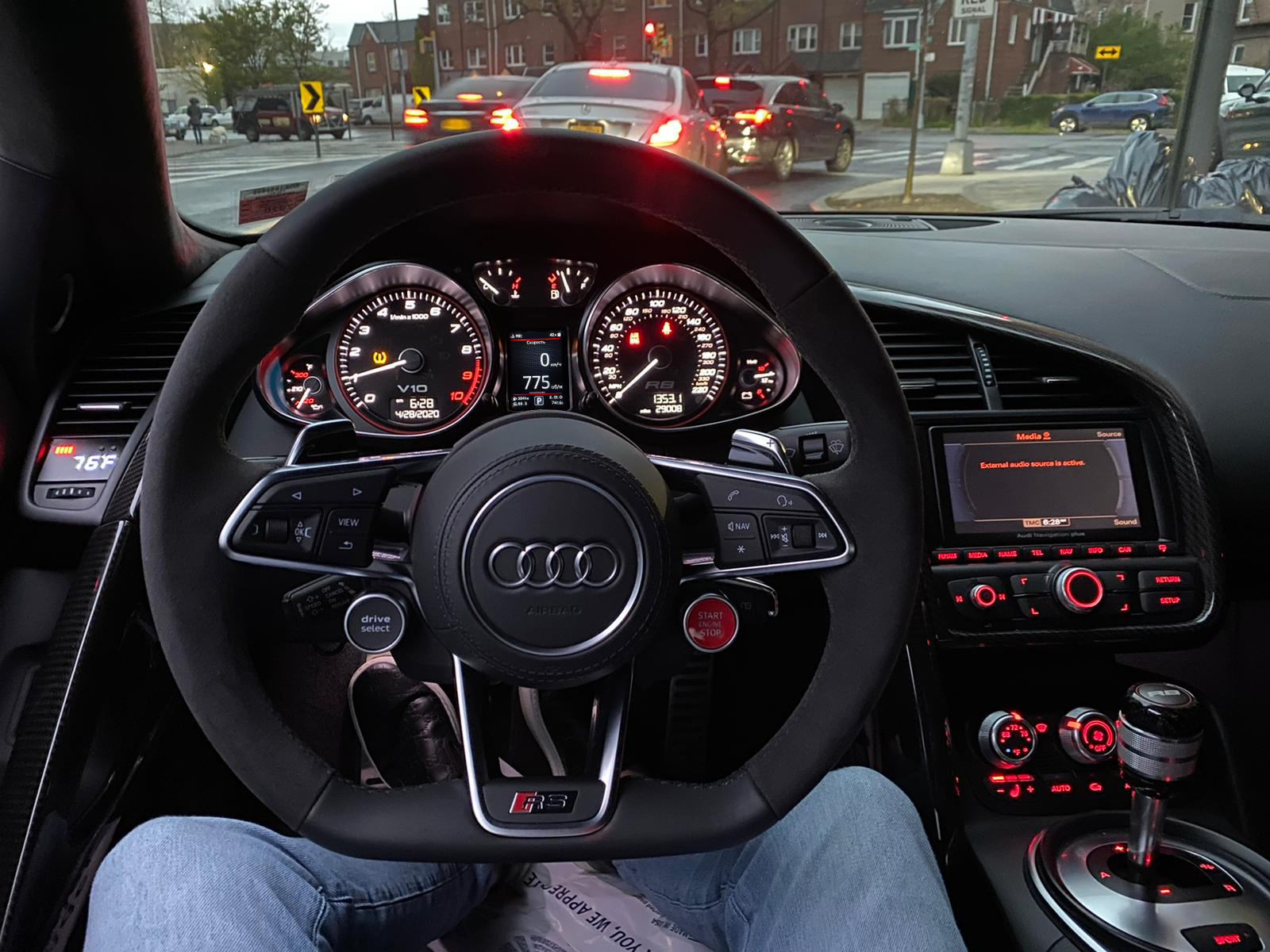
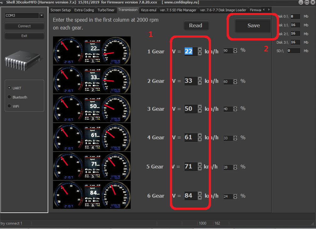
In cars with manual gearbox,
the ECU has no information about which gear you have selected, and
3dMFD cannot read it,
so 3dMFD shows the selected gear in terms of the ratio of driving
speed to RPM.
To calibrate, you must enter the travel speed in each gear at 2000
RPM in the first column.
Also, 3dmfd does not mean that neutral gear is engaged.
Only when you press the clutch pedal does the N signal appear.
В автомобилях с механической коробкой передач ЭБУ
двигателя не имеет информации о том, какую передачу вы
выбрали,
и 3dMFD не может ее прочитать, поэтому 3dMFD показывает выбранную
передачу по соотношению скорости движения и оборотов
двигателя в минуту.
Для калибровки необходимо ввести в первую колонку скорость движения
на каждой передаче при 2000 об/мин.
Кроме того, 3dmfd не означает, что включена нейтральная передача.
Только при нажатии на педаль сцепления появляется сигнал N.
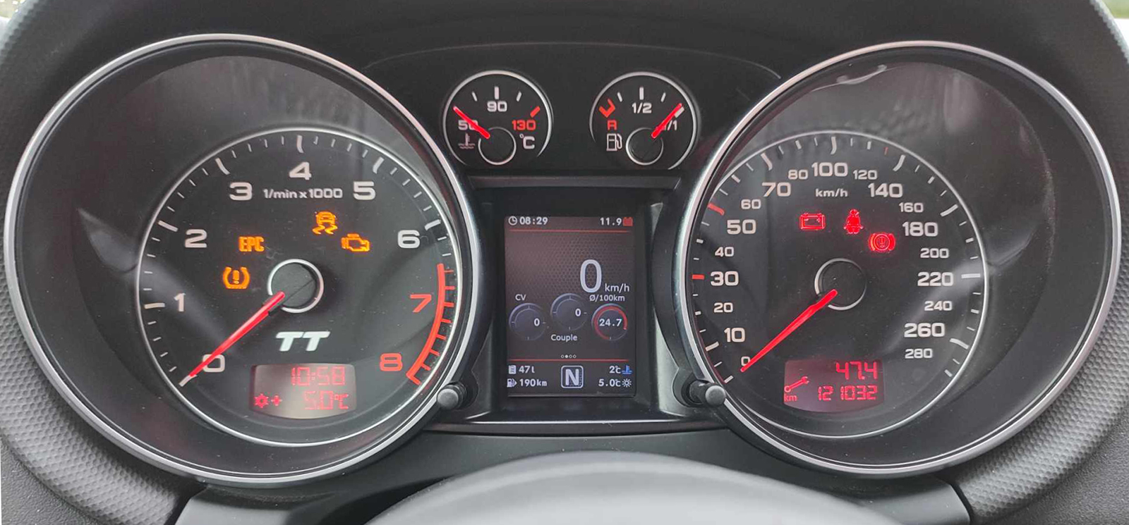
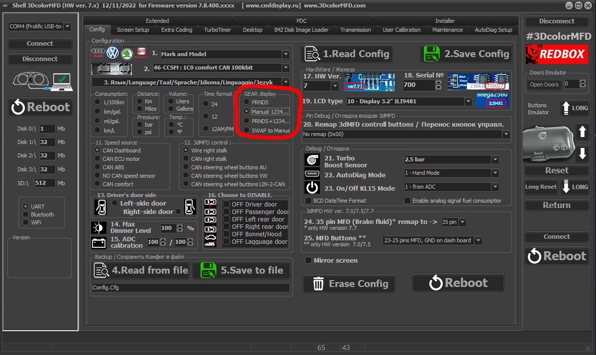
If the N signal does not appear when the clutch pedal is depressed.
Check the settings in the Config tab
Если при нажатии на педаль сцепления не появляется сигнал N.
проверте настройки во вкладке Конфиг
If the settings in the Configure tab are correct, but the N signal
does not appear when the clutch pedal is depressed.
Check if the clutch pedal micro switch is present and working.
Если настройк во вкладке Конфиг правильная, но при нажатии на
педаль сцепления не появляется сигнал N.
Проверте наличие и работоспособность микровыключателся педали
сцепления.
Then check everything
again
You can not turn the needles too quickly correcting the position,
you can damage the motors of the needles
You can not turn the needles, when there is power on the device.
13. Put back the cluster glass and put the cluster back into the
car.
14.Take a photo and post it on all social networks.
Go to auto club meeting and brag to your friends.
15. Show it to your girlfriend/wife with words: «Look what a cool
thing I bought for just 20 bucks! » =)
Затем проверьте все снова
Вы не можете поворачивать стрелки слишком быстро, исправляя
положение, вы можете повредить двигатели стрелки, а
так же нельзя поворачивать стрелки при включенной приборке.
13. Поставьте обратно стекло кластера и
вставьте кластер обратно в автомобиль. 14. Сфотографируйте и разместите его во всех
социальных сетях.Отправляйтесь
на встречу автоклуба и хвастайся друзьям. 15. Покажите это своей девушке / жене со
словами: "Посмотри, какую классную вещь я купил всего за 20 баксов!"
:)))


.jpg)