| |
You can place the adapter in the housing of the dashboard. |
|
| |
Вы можете разместить адаптер в корпусе приборной панели. |
|
| |
For the following reasons:
1. No need for a separate enclosure
2. New wiring can be easily routed along the vehicle's regular
harnesses
3. The extra harness will have 7 fewer wires (two power wires, two
CAN bus wires and three on-board computer control wires).
But later it turned out that the last three wires were not needed.
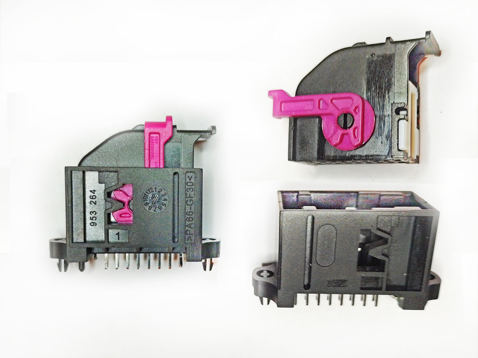
The mating (pin) part of the 18 pin connector 5Q0 972 718A can be
added to the dash. You should also have two of these connectors. |
|
| |
По следующим соображениям:
1. Не нужен отдельный корпус
2. Новую проводку легко проложить вдоль штатных жгутов автомобиля
3. Дополнительный жгут будет на 7 проводов меньше (два провода
питания, два провода CAN шины и три провода управления бортовым
компьютером.)
Но в дальнейшем выяснилось, что последние три провода не нужны.
В приборную панель можно добавить ответную (штыревую) часть 18
Pinового разъёма 5Q0 972 718A. Этих разъёмов также следует иметь две
штуки. |
|
| |
 |
|
| |
This connector and the mating part can be purchased on
Aliexpress.
https://www.aliexpress.com/item/4001312918765.html?sub=46ruipmq84872xv2qb0pqyqfc0q5vwbw&af=1954_2679416&utm_campaign=1954_2679416&aff_platform=api-new-link-generate&utm_medium=cpa&cn=2ururuipmq4y6tfyqnm1r2qkpozkng7d&dp=2ururuipmq4y6tfyqnm1r2qkpozkng7d&aff_fcid=a47de2ce7d5a425f8716278565fc65bc-1683848259356-07258-_DFBXlvL&cv=2&aff_fsk=_DFBXlvL&sk=_DFBXlvL&aff_trace_key=a47de2ce7d5a425f8716278565fc65bc-1683848259356-07258-_DFBXlvL&terminal_id=ec1e7e828a1c4399b4d960d8787177f6&utm_content=2&utm_source=aerkol&sku_id=12000026397389455
or add only the USB connector and lead the rest of the wires through
the free pins of the connectors T32 (blue) and T32a (green) of the
dashboard. It is better to search and check the free contacts before
any installation.
Mounting the adapter is much easier to do at the same time as
3DColorMDF, but I had it already installed and decided to do a
complete re-installation.
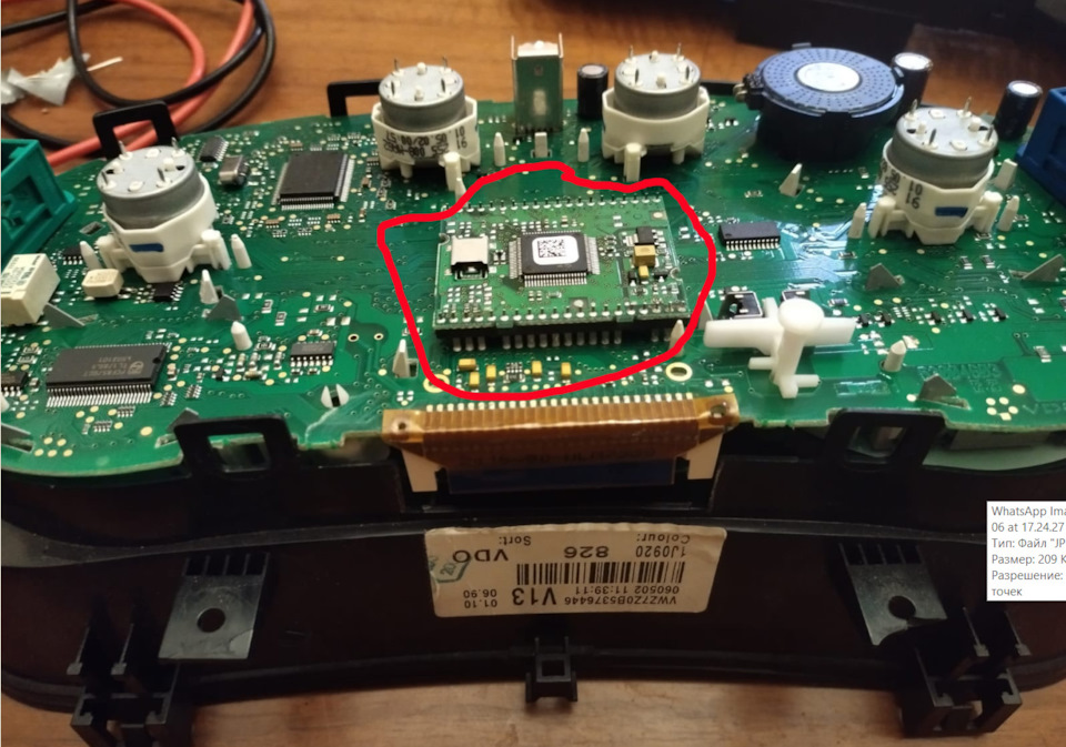
Unfortunately the pinout tables for the dashboard connectors that
can be found on the internet are not all true.
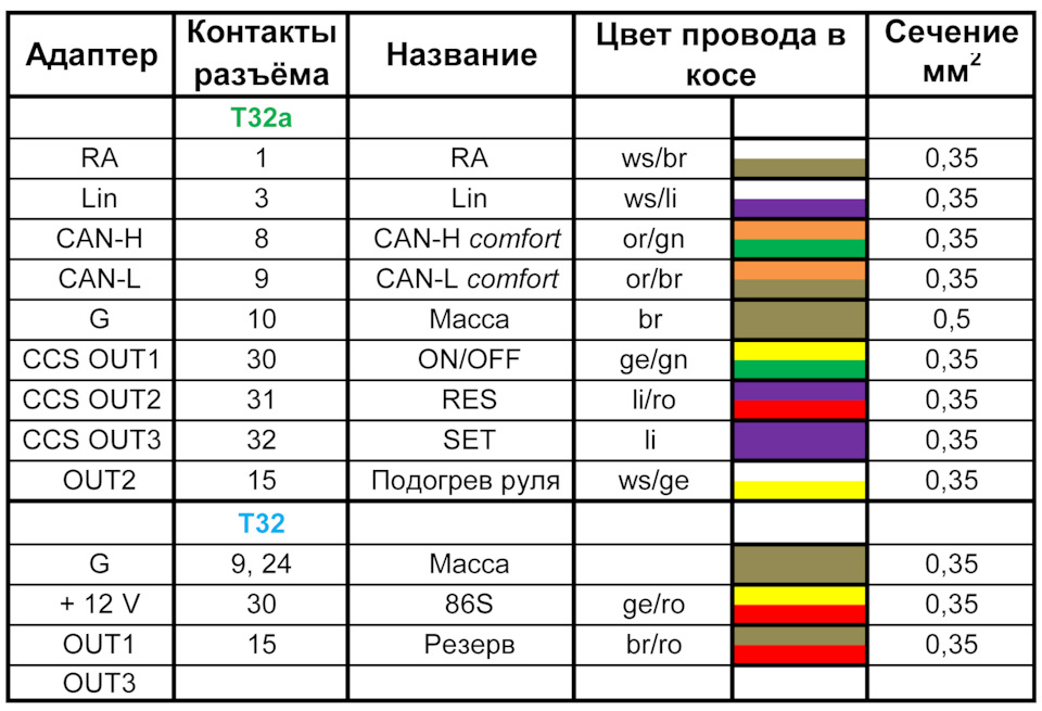
I had the following pins which I had planned to use:
On the T32 (blue) - pin 15
On the T32a (green) - 1, 3, and 10 pins. Pin 10 sat on the ground.
And pins 30, 31, and 32 on the T32a connector were loose.
This is on the instrument panels 1J0 920 826, 1J0 920 826A and 1J5
920 826A. On the other dashboards have not checked (for lack of them).
As cooller01 and VampireLo explained, pins 30, 31 and 32 on the T32a
connector were only used on dashboards with a full screen.
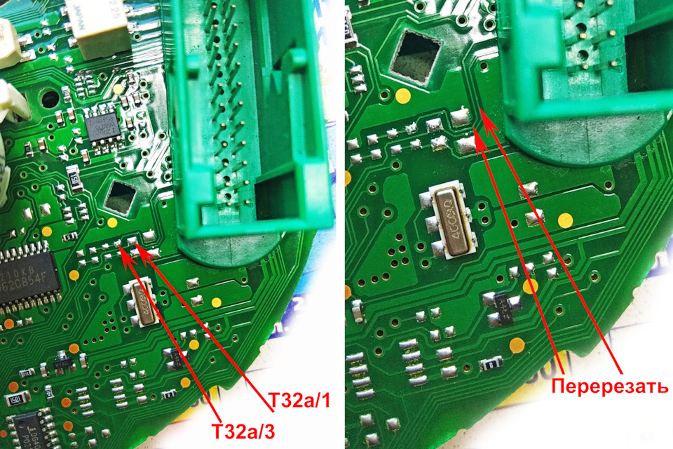
T32a/15 is only used in 3DColorMDF (pin 25 MFD Turbo) for diesels,
and since I have gasoline, I used it. At pins 1 and 3 of the T32a
connector and at pin 13 of the T32 connector, I cut the tracks
leading to those pins: |
|
| |
Этот разъём с ответной частью можно приобрести на Али .
https://www.aliexpress.com/item/4001312918765.html?sub=46ruipmq84872xv2qb0pqyqfc0q5vwbw&af=1954_2679416&utm_campaign=1954_2679416&aff_platform=api-new-link-generate&utm_medium=cpa&cn=2ururuipmq4y6tfyqnm1r2qkpozkng7d&dp=2ururuipmq4y6tfyqnm1r2qkpozkng7d&aff_fcid=a47de2ce7d5a425f8716278565fc65bc-1683848259356-07258-_DFBXlvL&cv=2&aff_fsk=_DFBXlvL&sk=_DFBXlvL&aff_trace_key=a47de2ce7d5a425f8716278565fc65bc-1683848259356-07258-_DFBXlvL&terminal_id=ec1e7e828a1c4399b4d960d8787177f6&utm_content=2&utm_source=aerkol&sku_id=12000026397389455
или добавить только разъём USB, а остальные провода вывести через
свободные контакты разъёмов Т32 (синий) и Т32а (зелёный) приборной
панели. Поиск и проверку свободных контактов лучше вести до любого
монтажа.
Монтаж адаптера значительно проще вести одновременно с 3DColorMDF,
но у меня он был уже установлен и я принял решение произвести полную
переустановку.
К сожалению гуляющие в интернете таблицы распиновки разъёмов
приборной панели не во всём соответствуют действительности.
У меня оказались не свободными следующие контакты, которые я наметил
к использованию:
На Т32 (синий) – 15 контакт
На Т32а (зелёный) – 1, 3, и 10 контакты. Контакт 10 сидел на массе.
А контакты 30, 31 и 32 на разъёме Т32а оказались свободными.
Это на приборных панелях 1J0 920 826, 1J0 920 826A и 1J5 920 826A.
На других приборных панелях не проверял (за не имением оных). По
разъяснениям cooller01 и VampireLo контакты 30, 31 и 32 на разъёме
Т32а использовались только на приборных панелях с полным экраном.
Т32а/15 задействуется в 3DColorMDF (25 контакт MFD Turbo) только для
дизелей, а т.к. у меня бензин, то я его использовал. У контактов 1 и
3 разъёма Т32а и у контакта 13 разъёма Т32 перерезал дорожки,
ведущие к этим контактам: |
|
| |
 |
|
| |
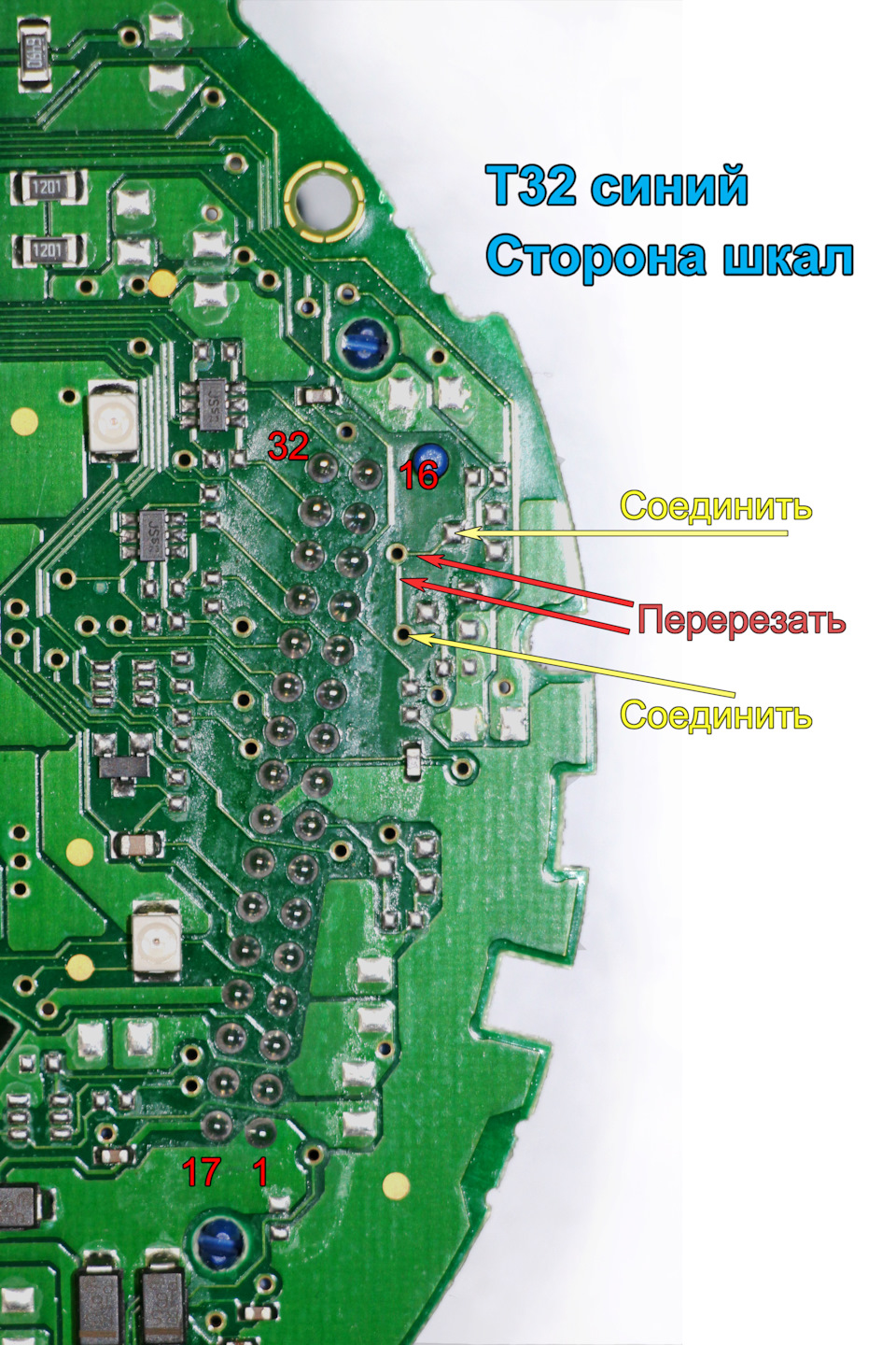
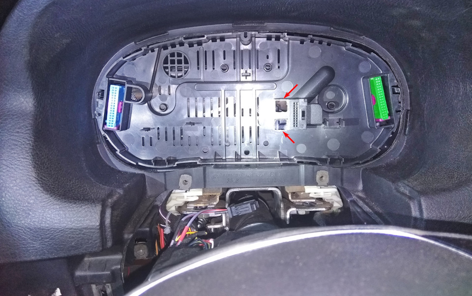
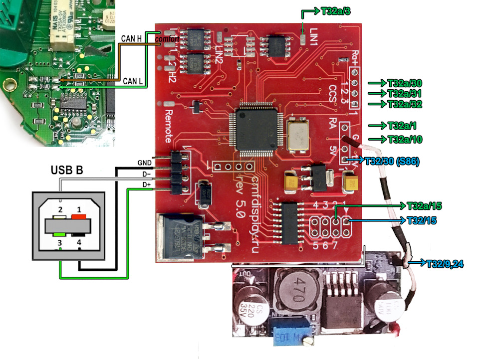
T32 pin 15 And connect the points marked with yellow arrows.
Connecting the adapter: |
|
| |
Т32 контакт 15 И соединяем точки отмеченные жёлтыми
стрелками.
Подключение адаптера: |
|
| |
 |
|
| |
 |
|
| |
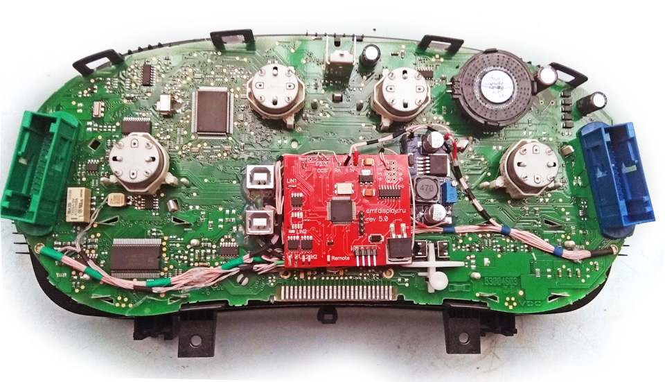
The CAN bus connection must be made with a twisted pair (twisted
together wires) and the connection made to alternative points on the
back of the dashboard to reduce the number of wires going to the
connectors. For ground I used a wire with a thicker cross section
and additionally used the contact T32a/10, already sitting on the
ground (from the outside of the dash, I ran a wire from this contact
to the ground terminal). Maybe it's over-insurance, but 3DColorMDF
and the adapter can control relays (one for 3DColorMDF and up to
seven for the adapter), and the operating current of each relay is
120 - 160 mA. The +12 volt goes to the relay outside the dashboard,
but the current to the ground in this case goes through it. From the
contacts I led only one wire and then, if necessary, made a
branching. The current consumption of the 3DColorMDF module in full
working condition at 12 volts is about 100 mA, and the adapter is
about 50 mA. |
|
| |
Подключение CAN шины обязательно выполнить витой парой (скрученными
вместе проводами) и подключение делал к альтернативным точкам на
тыльной стороне платы приборки, чтобы уменьшить количество проводов
идущих к разъёмам. Для массы использовал провод более толстого
сечения и дополнительно задействовал уже сидящий на массе контакт
Т32а/10 (снаружи приборки проложил провод от этого контакта к клемме
масса). Может это и перестраховка, но 3DColorMDF и адаптер могут
управлять реле (одно у 3DColorMDF и до семи у адаптера), а ток
срабатывания каждого реле 120 – 160 mA. +12 вольт идёт на реле вне
приборной панели, но ток на массу проходит в данном случае через
неё. От контактов вёл только по одному проводу и далее, в случае
необходимости делал разветвление. Ток потребления модуля 3DColorMDF
в полном рабочем состоянии по 12 вольтам примерно 100 mA, а адаптер
в районе 50 mA. |
|
| |
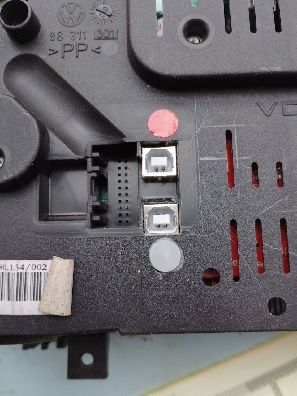
Installed the USB B connectors
In the back cover of the dashboard cut holes for them and make
markings, |
|
| |
Установил разъёмы USB B
В задней крышке приборной панели прорезаем отверстия под них и
делаем маркировку, |
|
| |
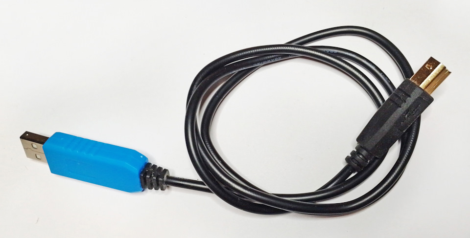
And on the "blue cord" USB COM-port emulator included in the kit
install cable connector USB B |
|
| |
А на “синий шнурок” USB COM-port эмулятор идущий в комплекте
устанавливаем кабельный разъём USB B |
|
| |
So we put the back cover of the dashboard in place and make a mark
for the cutouts |
|
| |
Прикладываем заднюю крышку приборной панели на место и делаем
разметку под вырезы |
|
| |
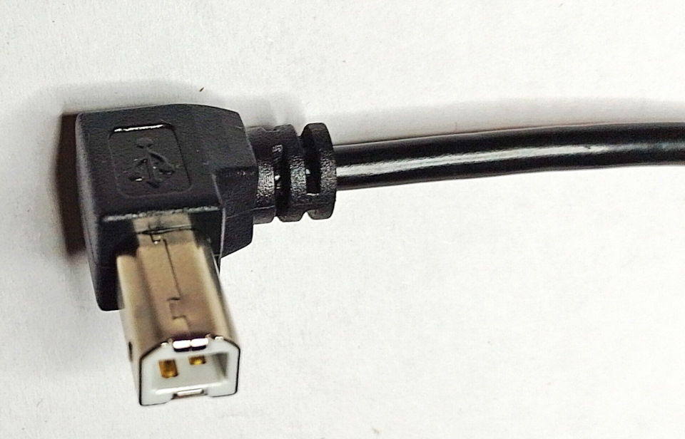
You can use angle connectors: |
|
| |
Можно использовать угловые разъёмы: |
|
| |
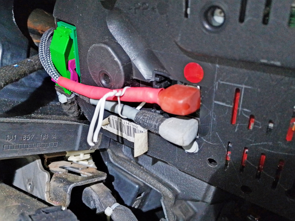
From the connectors T32 and T32a of the dashboard, lay the wires we
need:
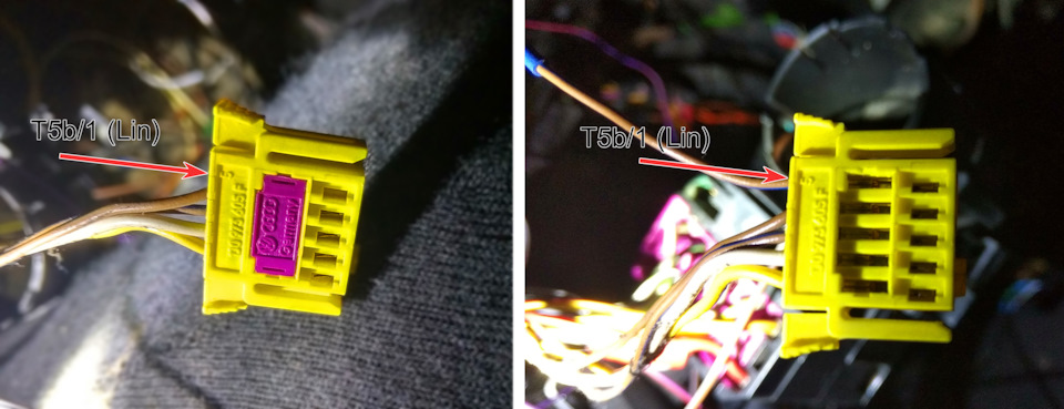
To the T5/b connector (1J0 973 605F - interior side steering wheel
connector) |
|
| |
От разъёмов T32 и T32a приборной прокладываем нужные нам провода:
В разъём T5/b (1J0 973 605F — разъём подрулевого шлейфа со стороны
салона) |
|
| |
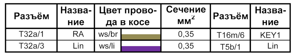
To pin out the connector remove the colored insert
add the first contact with the wire - bus Lin and connect it to
T32a/3. To pin the connector remove the colored insert.
From T32a/1 (Ra is the output of the digital potentiometer) pull the
wire to the KEY1 (T16m/6) input of the radio. T16m is the 16 pin
connector of the radio (Isudar T72). And we run the rest of the
wires (about which in the next part). |
|
| |
Для распиновки разъёма удалите цветную вставку
добавляем первый контакт с проводом – шина Lin и соединяем его с
T32a/3. Для распиновки разъёма необходимо удалить цветную вставку.
От T32a/1 (Ra — выход цифрового потенциометра) тянем провод к входу
KEY1 (T16m/6) магнитолы. T16m – шестнадцати контактный раъём
магнитолы (Isudar T72). И прокладываем остальные провода (о чём в
следующей части). |
|
| |
Putting the dashboard back |
|
| |
Ставим приборную панель на место |
|
| |
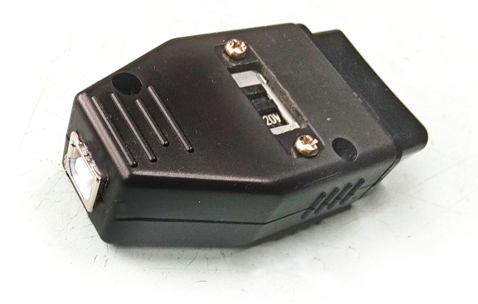
And as for the hidden installation, you can use the free pins in the
connector OBDII and make an adapter for this. |
|
| |
А так же для скрытого монтажа можно использовать свободные пины в
разъёме OBDII и сделат ьпереходник для этого. |
|
| |
Author / Автор статьи Dimirty https://www.drive2.ru/l/634100176562172688/ |
|
|