VW 
1. Passat B5+(B5.5;3bg; Fl) IMMO3 - VDO

1.1 Passat B5(B5;3b)IMMO2 - VDO

VW 
2. Golf4, Bora, Jetta IV (4.5 Brasil) IMMO3 - VDO

2.2 Golf4 , Bora, Jetta IV IMMO2 - VDO
2.3 Golf4 , Bora, Jetta IV IMMO2 - BOSH
2.4 Golf4 , Bora, Jetta IV IMMO2 - Motometer

VW 
3. T4 (2000-2005)
4. Sharan (2001-2003)
5. T5 (2003-2010)

6. Polo (9N, 9N3)
Skoda
1.Octavia MK1
2. Fabia MK1
3. Superb MK1
Seat
1. Leon 1M
2. Cupra R 1M
3. Toledo< 1M
Audi
1. Audi TT
(8N)

2. Audi A3/S3 (8L)
3. Audi A4/S4/RS4 B5 (8D)

4. Audi
A4/S4/RS4 B6/B7 (8E)
5. Audi A6/S6/RS6 C5 (4B)

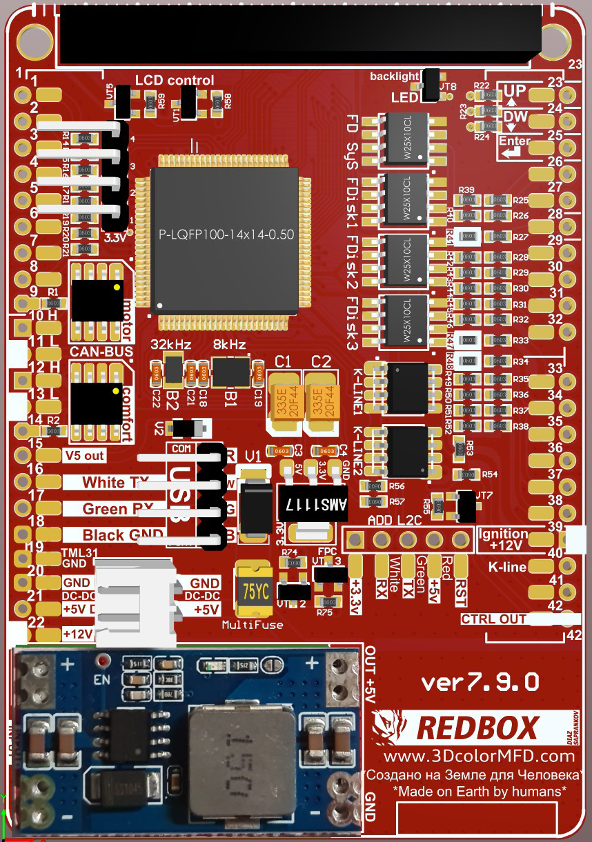
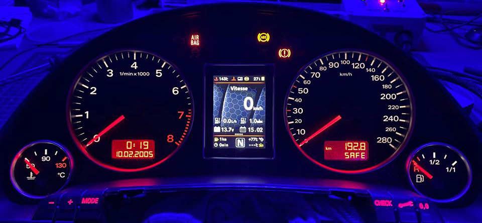
3DColorMFD ver. 7.9.0

Plug&Play

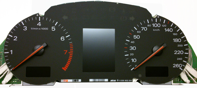
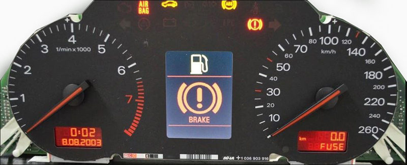
Audi - A4/S4/RS4 B6/B7 (8E)


You will need:
 

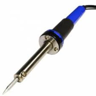
Soldering iron 40 W

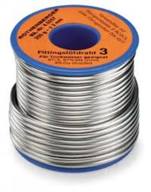
Tin

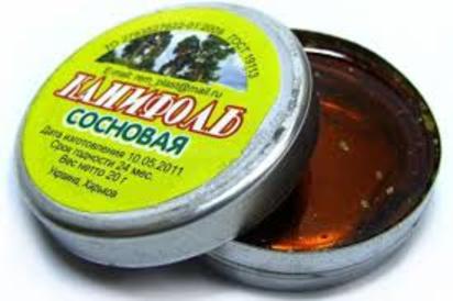
Flux

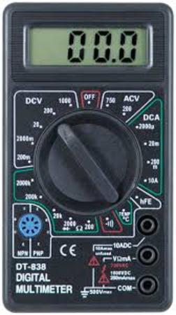
Multimetr

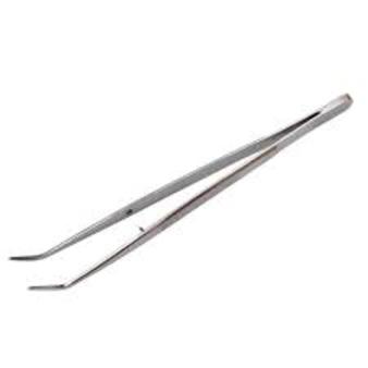
Tweezers
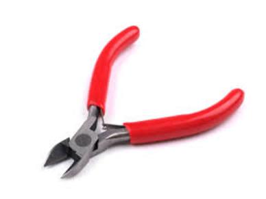
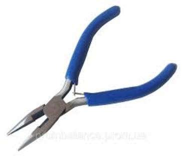
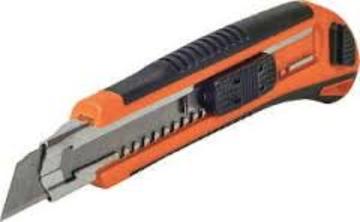
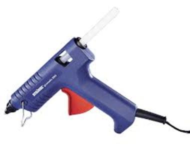
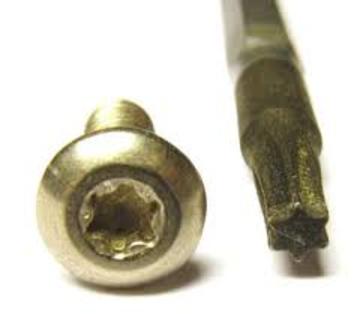
Nippers Pliers Knife Thermocouples And screwdriver Torx T10

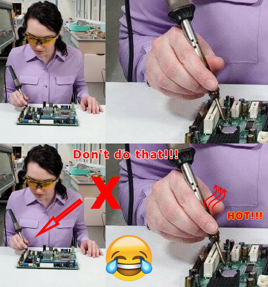
Safety precautions

DO NOT!


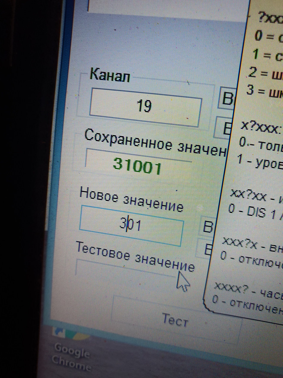
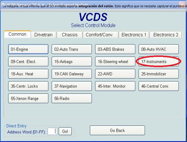
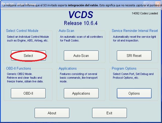
On some cars it is necessary to record the cluster to disable the factory FIS. On B6 this is not very important. On B7 this must be changed. Using VAG-Com ( VCDS) check/modify the following values.

17-Instrument 
10-Adapation 
Channel 19 
x? xxx: 
On-board computer 
0 - only level 2 (long-term memory) 
1 - levels 1 and 2

xx? xx: Driver information system (DIS) 
0 - DIS 1 
1 - Highline without DIS 
2 - DIS 2 


Change these values so the second digit is either 1 or 0 and their digit is O thus giving x10xxx or x00xx (x10xx works better). The x's will remain unchanged from
Using VAG-COM (VCDS) in 19th adaptation channel, switch the cluster to "trip 1 and trip 2" mode and
"Only DIS 1" (Second number = 1 and third numbers = 0)


vazik43


Sorry for the quality of the video, if you can do better write me diazx@ya.ru
Извините за качкство видео ,если вы можете сделать лучше напишите мне diazx@ya.ru

(Following info from Remnevolt on Drive2.ru)


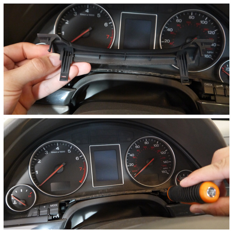
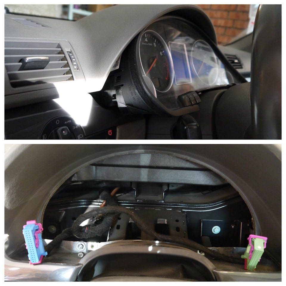
  To remove the tidy, you need to remove the plastic strip above the steering column (latches), Unscrew the two torcs that hold the dashboard and then slowly and carefully pull it towards you.
Plus, do not forget to push the steering column as far as possible towards you and down and I strongly advise you to glue it with masking tape IN ADVANCE and put a thin cloth, as the risk of scratching the paint tends to 100%. Then we snap off the connectors - here they are perfect, no side tabs, a plastic bracket that needs to be thrown off and then removed from the shield.
Чтобы снять приборку нужно снять пластиковую планку над рулевой колонкой (на защёлках), Открутить два торкса которые держат приборную панель и затем медленно и аккуратно тянуть её на себя.
Плюс не забудьте выдвинуть рулевую колонку максимально на себя и вниз и очень советую ЗАРАНЕЕ обклеить её малярным скотчем и подложить тоненькую тряпочку, так как риск поцарапать краску стремится к 100%. Далее отщёлкиваем разъёмы — вот они идеальны, никаких боковых язычков, пластиковая скоба, которую нужно скинуть и затем вынуть разъём из щитка.


(Алексей) https://www.drive2.ru/l/529786209900167450/


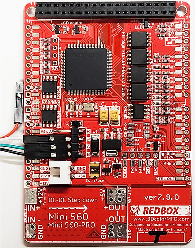
ATTENTION!!! When installing a color 3dMFD, there are 3 most important points.

1. You need to configure the power supply to 5.5v.
The 3DcolorMFD operates at a voltage of
5.5v. When you connect the power supply to the
3DcolorMFD you should make sure that the output from DC-DC power supply is 5.5v, otherwise it will damage the processor! Paragraph 18
2. It is necessary to rinse all soldering points. Install with extreme caution.
After soldering the wires, be sure to rinse the soldering points with special flushing agents, or isopropyl alcohol. During flushing, do not allow alcohol to get on the display or under the display and its board!

При установке цветного MFD есть 3 самых важных пункта:

1. Нужно настроить блок питания на 5.5в.

3DcolorMFD работает на напряжении 5.5в. Кода вы подключаете блок питания к 3DcolorMFD, вы должны убедиться в том, что на выходе DC-DC блока питания напряжение 5.5в, иначе это приведет к повреждению процессора!

2. Нужно промыть все места пайки. Устанавливать предельно осторожно.

После пайки проводов обязательно промыть места пайки специальными промывочными средствами или изопропиловым спиртом. Во время промывки не допускать попадания спирта на дисплей или под дисплей и его плату!


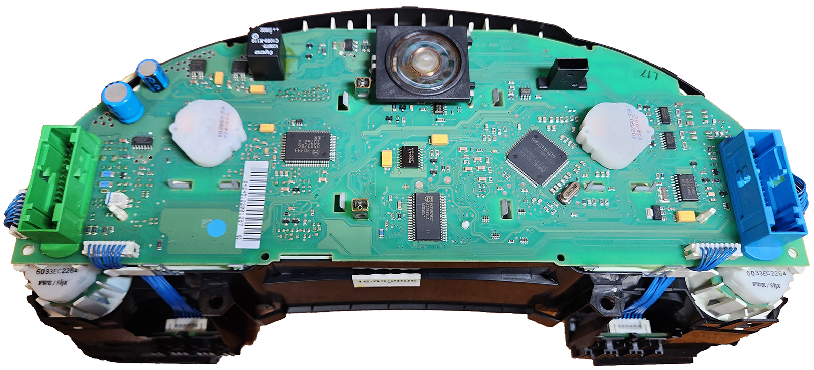
1. Disassemble the cluster.

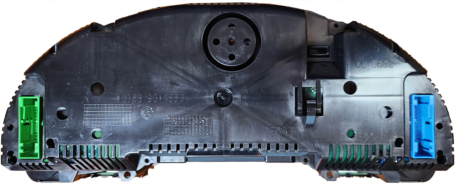
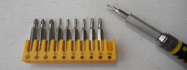
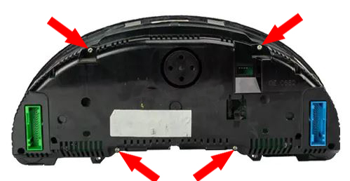
1.1 With a screwdriver torx T10, unscrew the two screws edges on the rear of the instrument panel.

1. Разбираем приборку

1.1. Используйте отвертку ТОРКС Т10

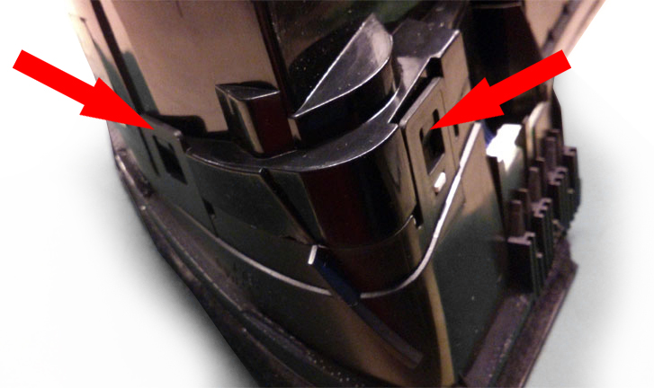
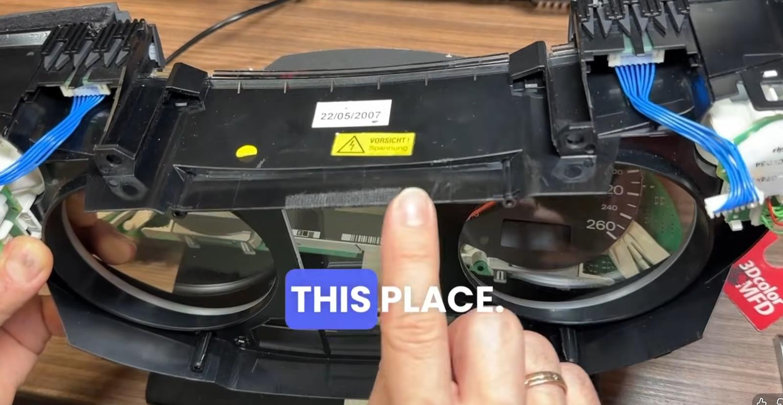
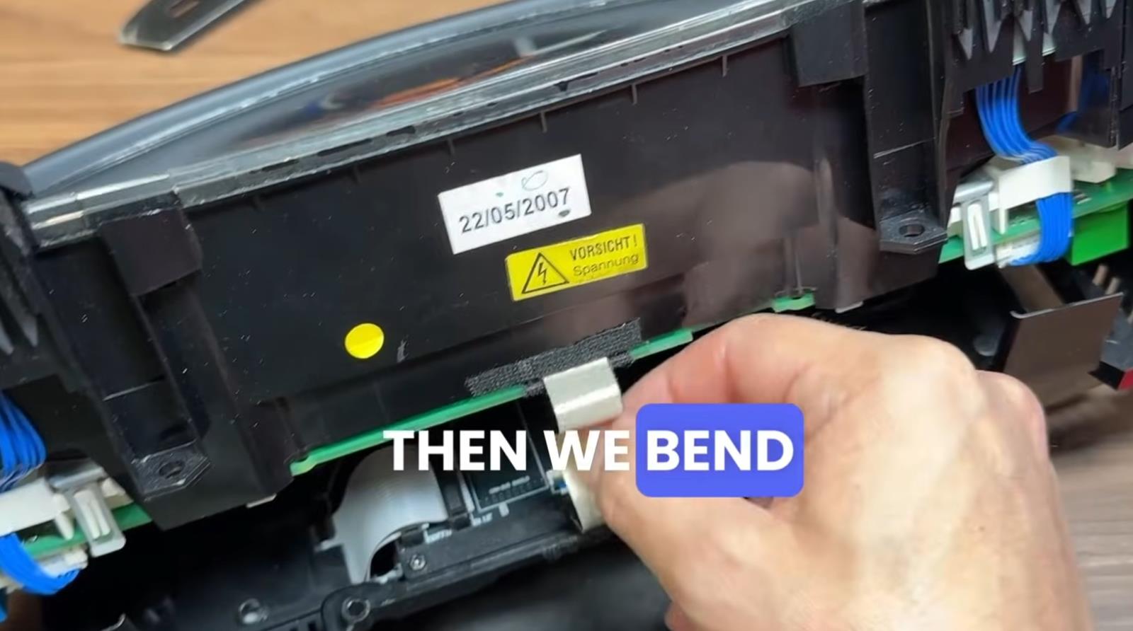
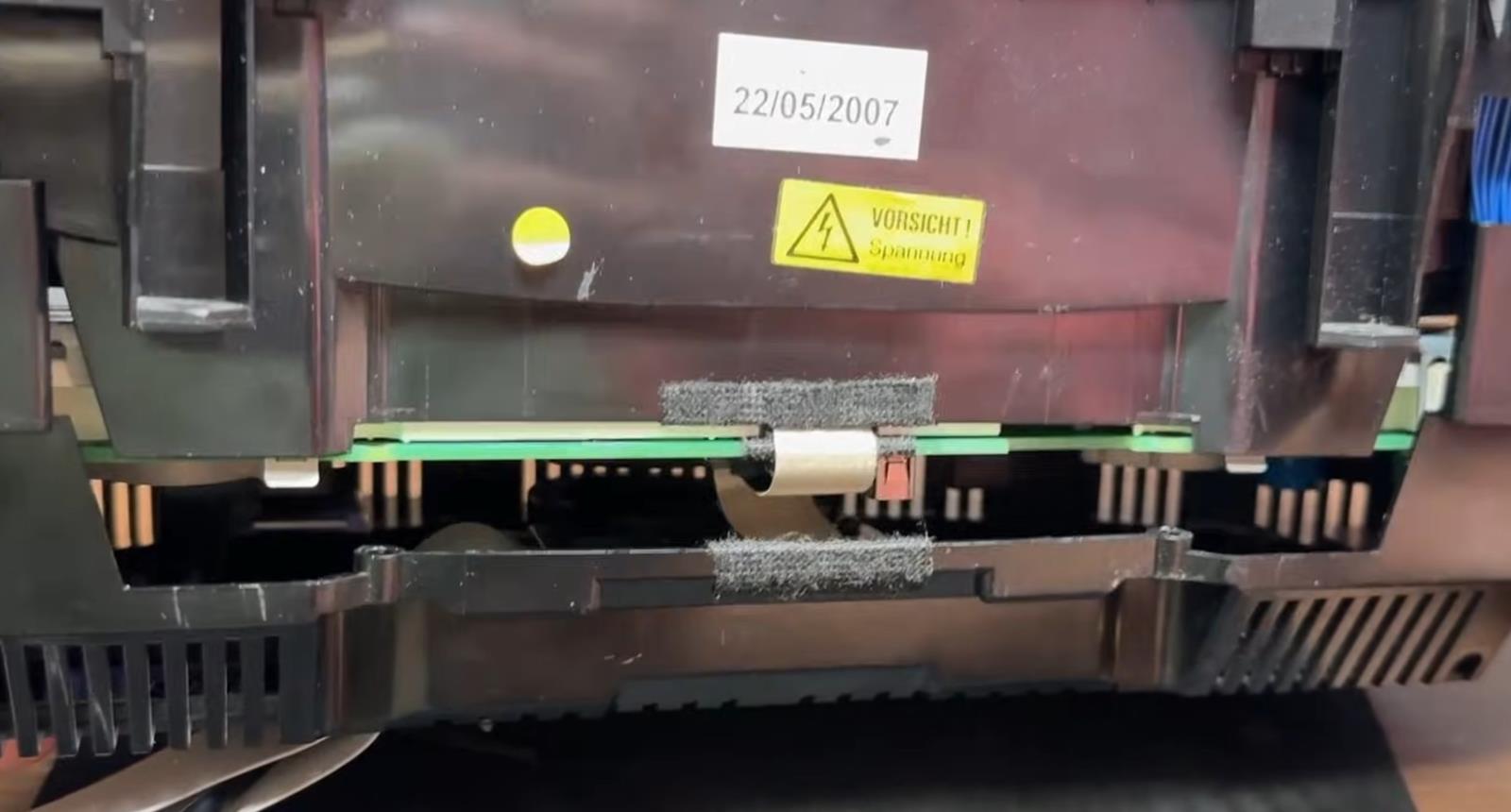
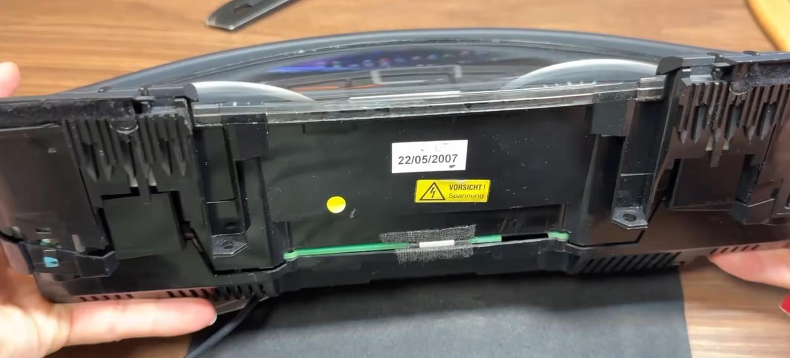
Bend all the latches neatly remove the front of the case with glass

View from above


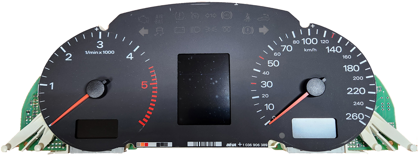
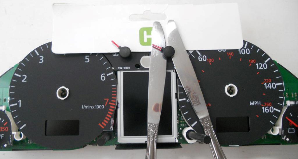
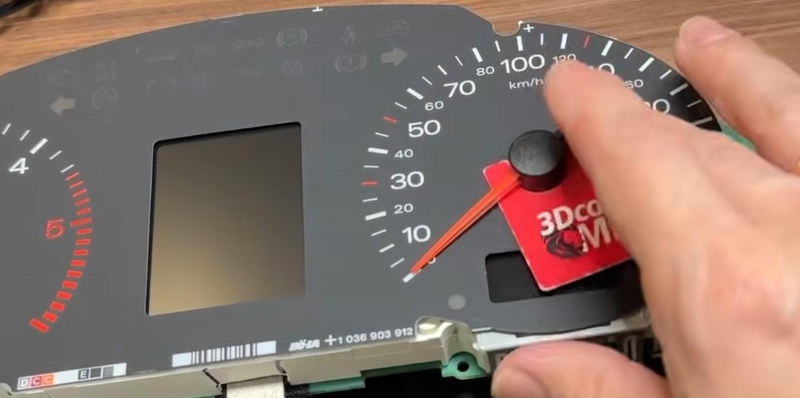
1.2 Remove the needles.
There are 2 ways to do it:

  • scroll counter-clockwise and simultaneously pull it to yurself or
  • using using non sharp butter knives or spatula, shoot the arrows from their shafts. Its better to put paper between the knives and the base of the device to avoid damaging it.
    Pull the arrows up to yourself.

1.2 Удалите стрелки.
Сделать это можно двумя способами:
Крутите против часовой стрелки и одновременно потяните на себя


Или используя неострые ножи для масла или лопатку.
Лучше положить бумагу между ножами и основанием устройства, чтобы не повредить его.
Вытяните стрелки к себе.


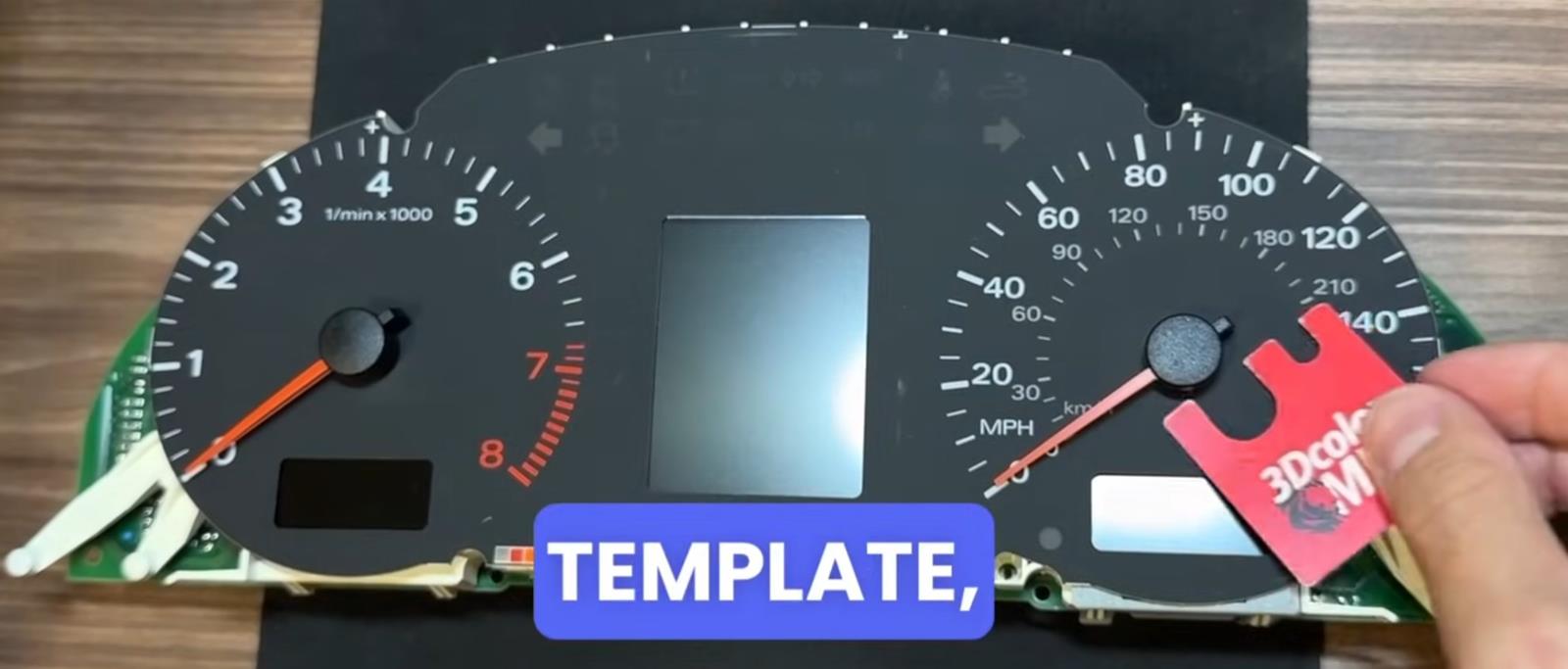
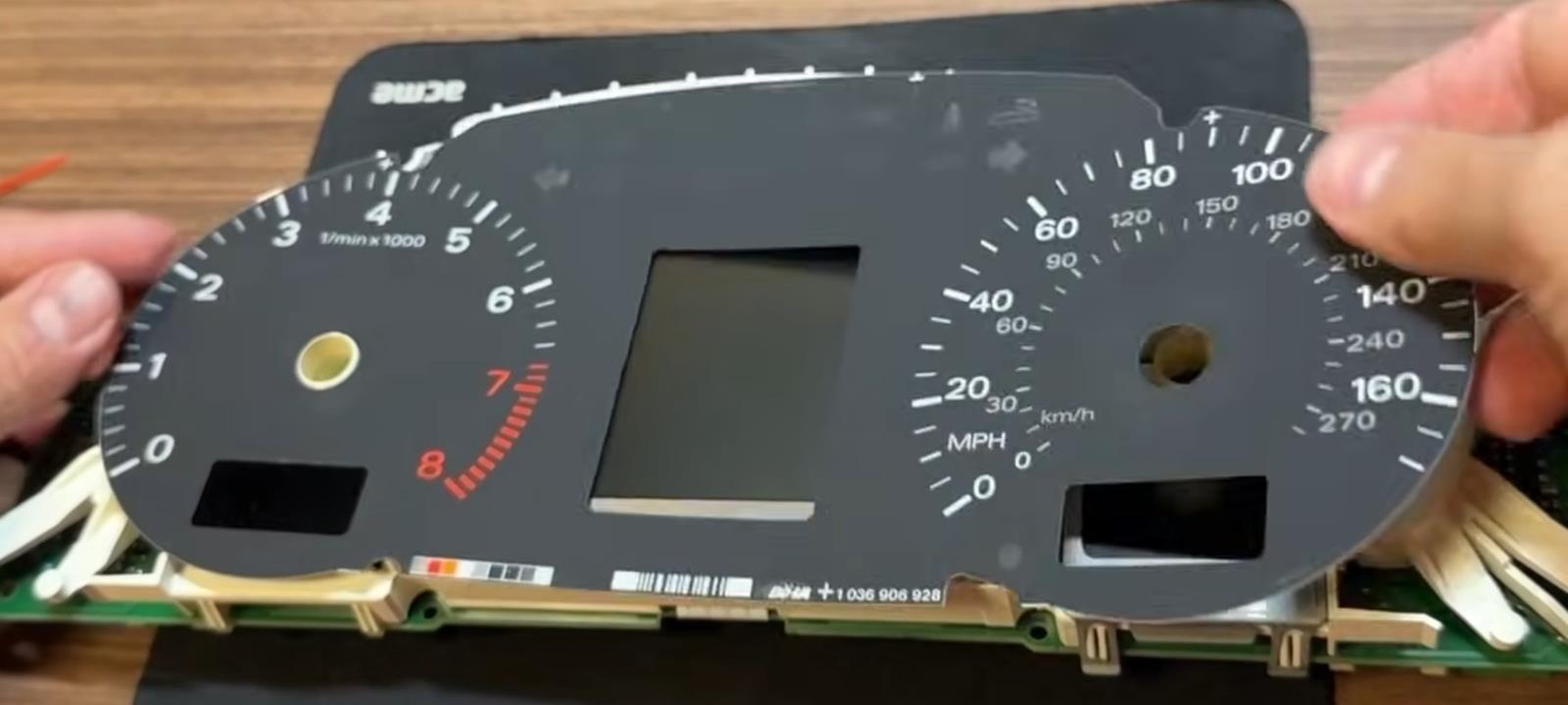
1.3. Then remove the substrate.
Удалите шкалы.


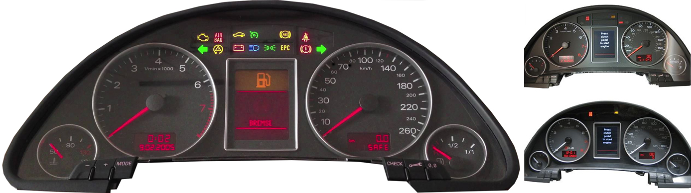
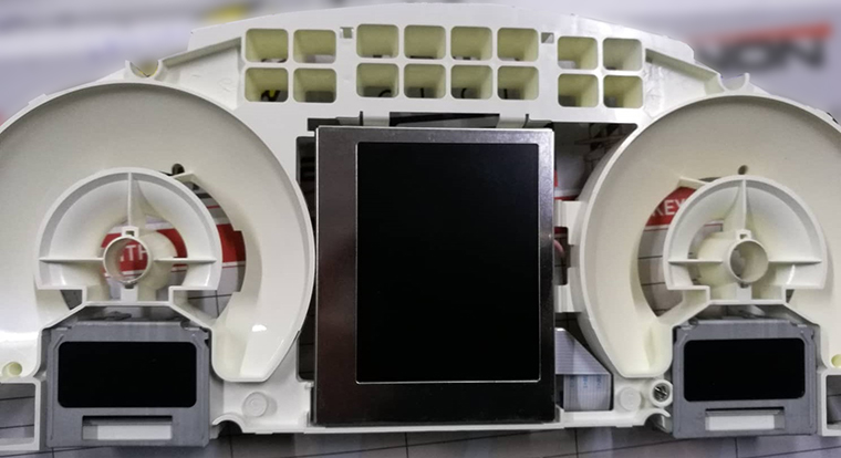
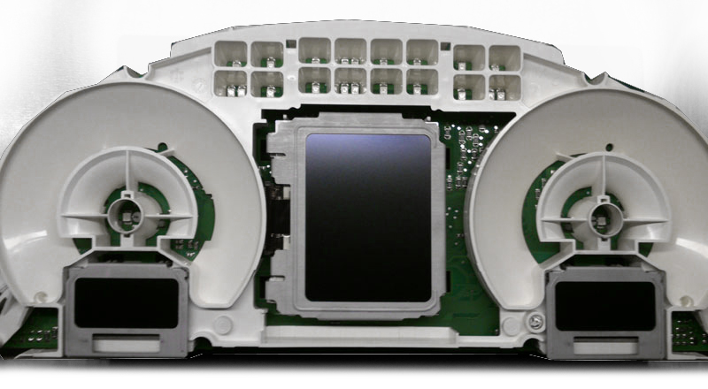
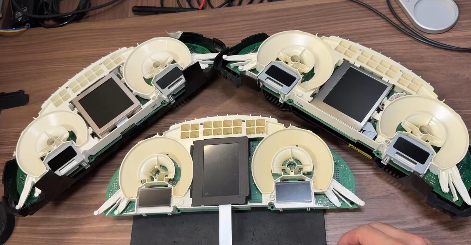
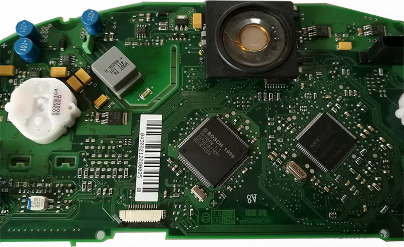
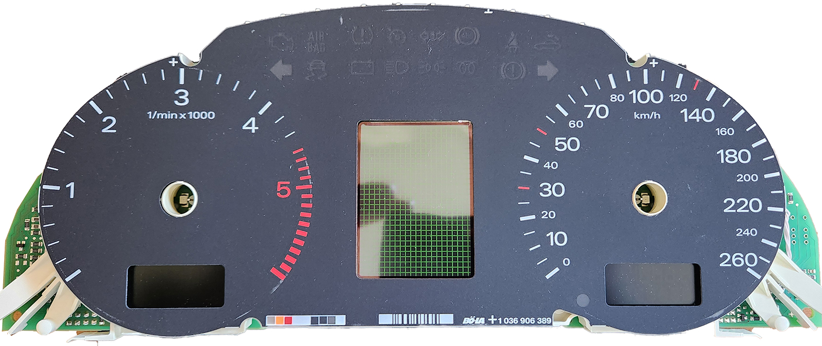
3 different types of instrument panels
3 разных типа приборных панелей


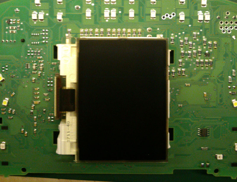
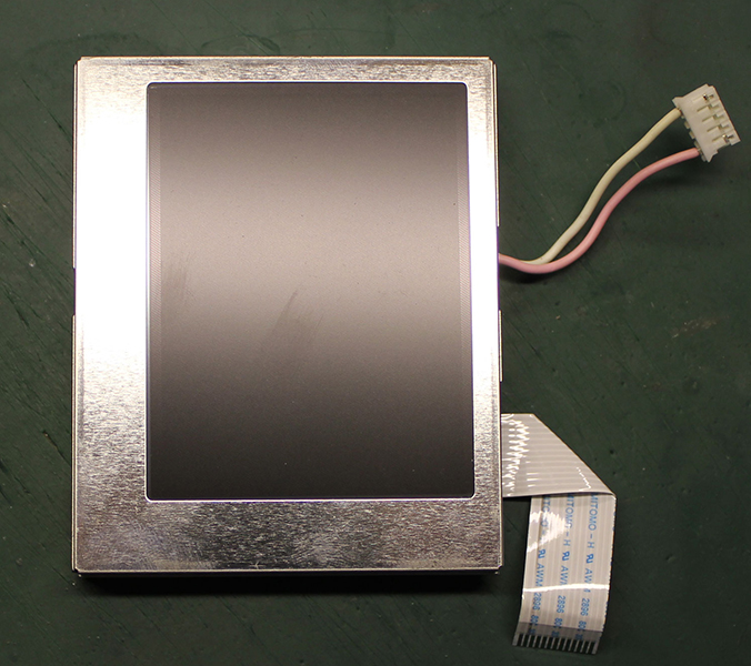
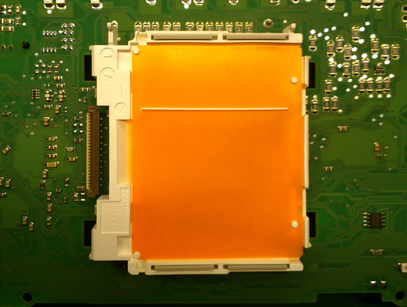
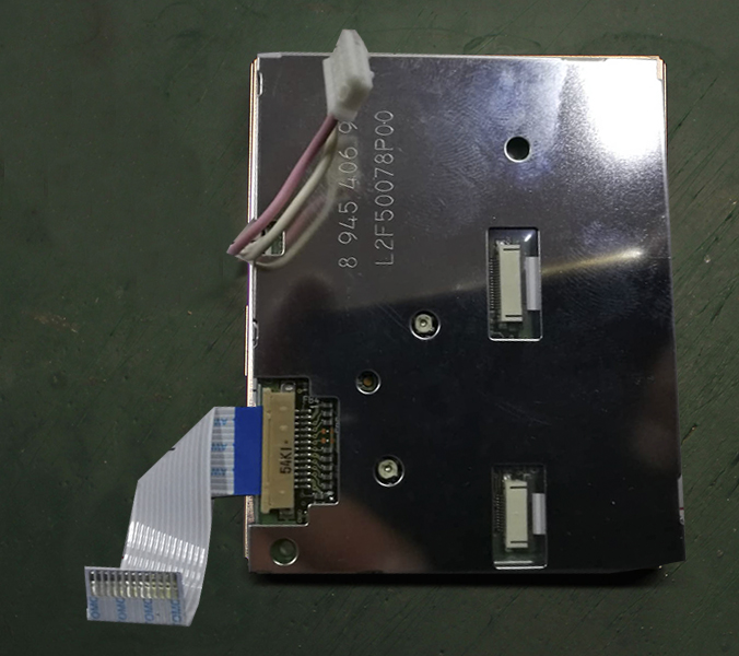
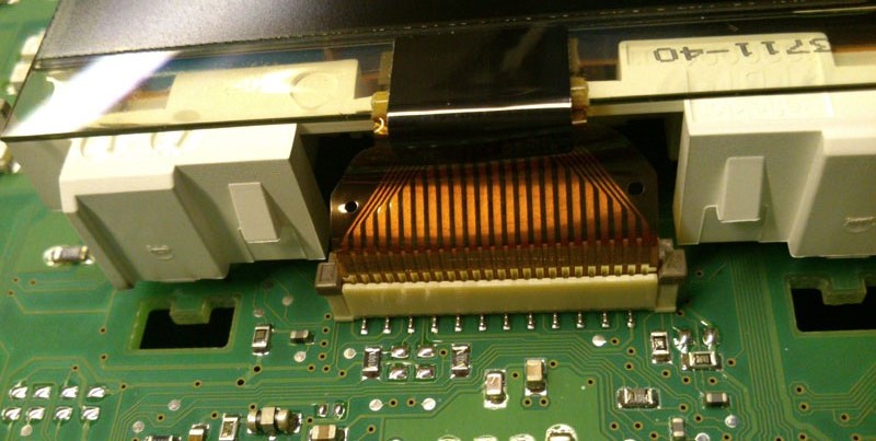
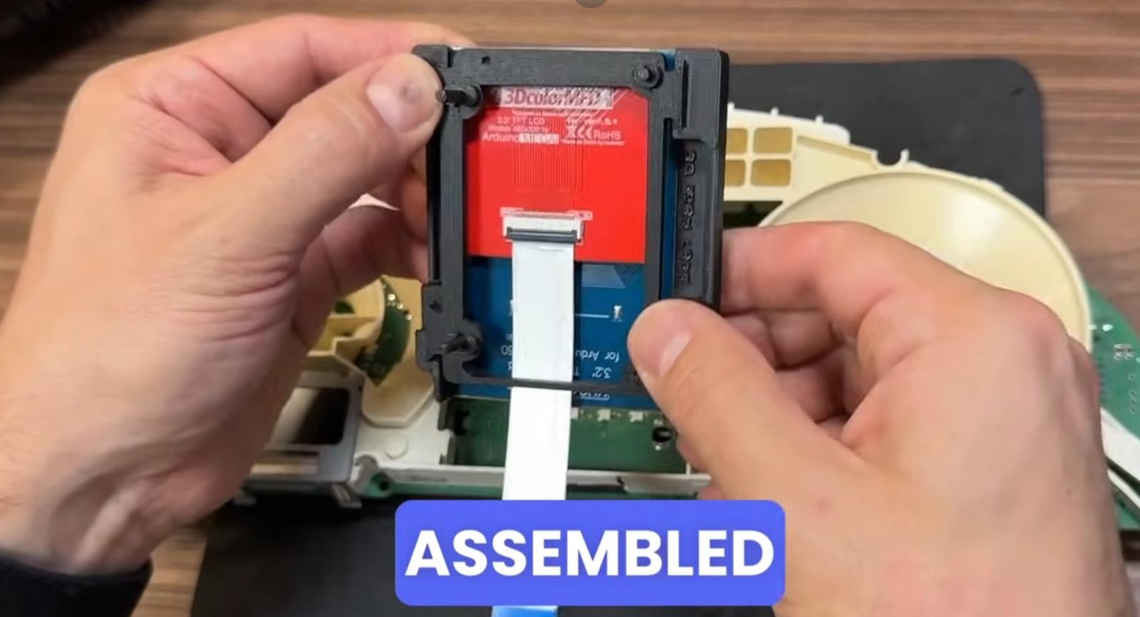
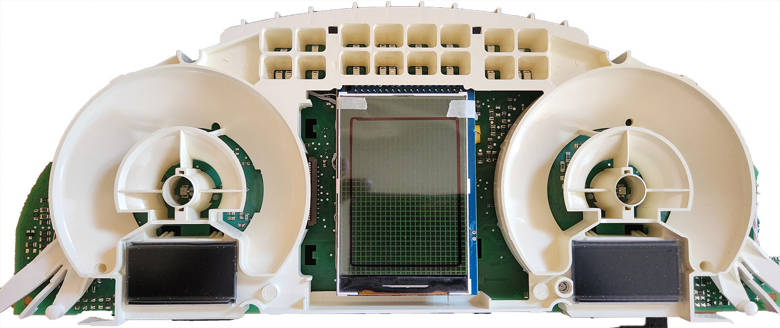
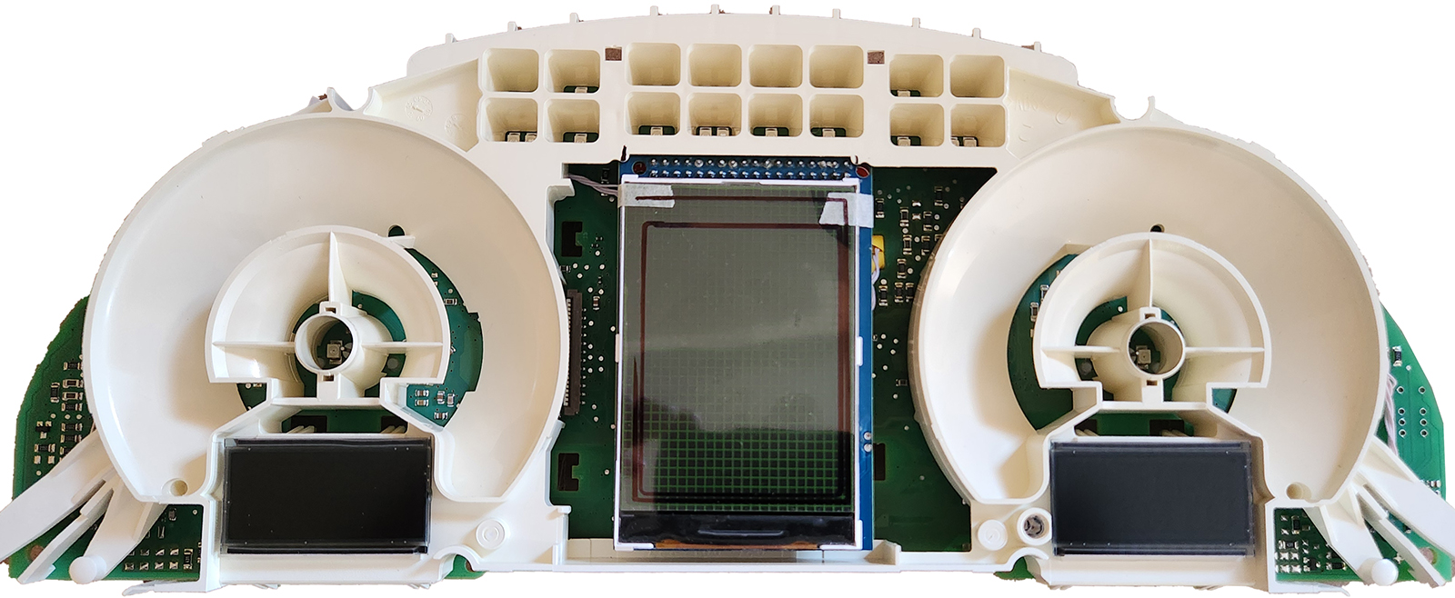
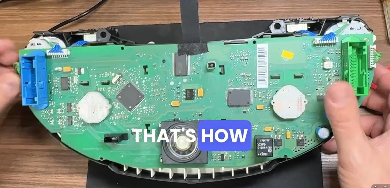
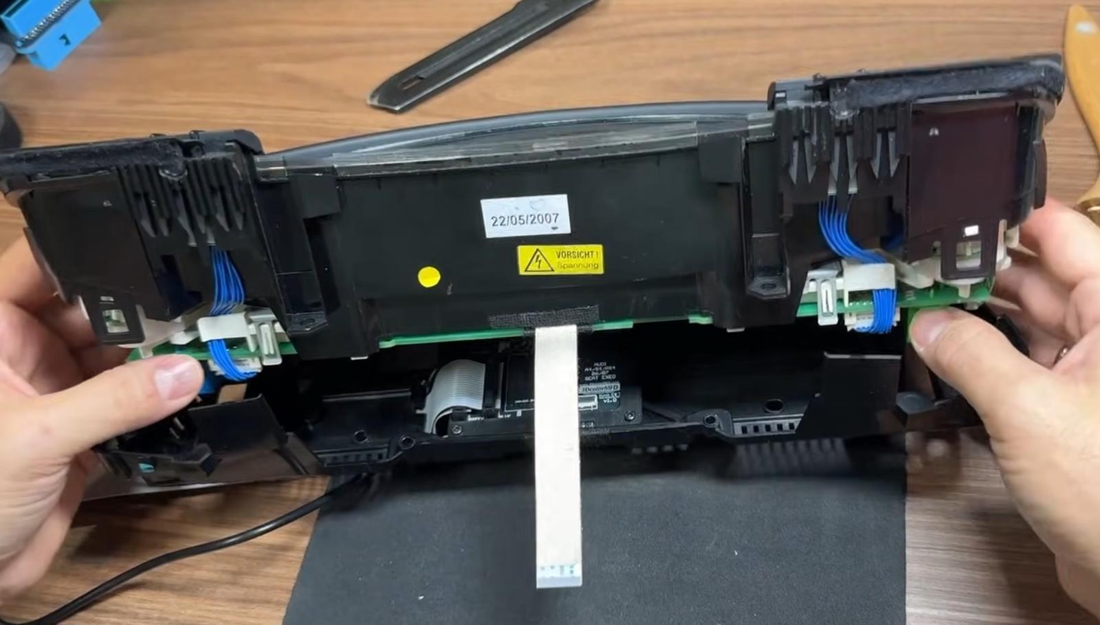
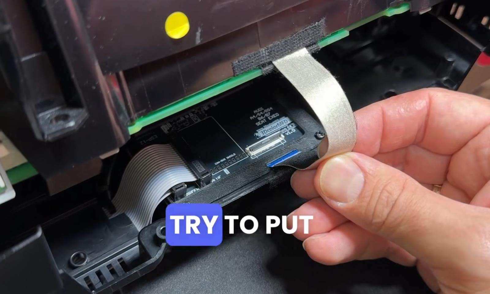
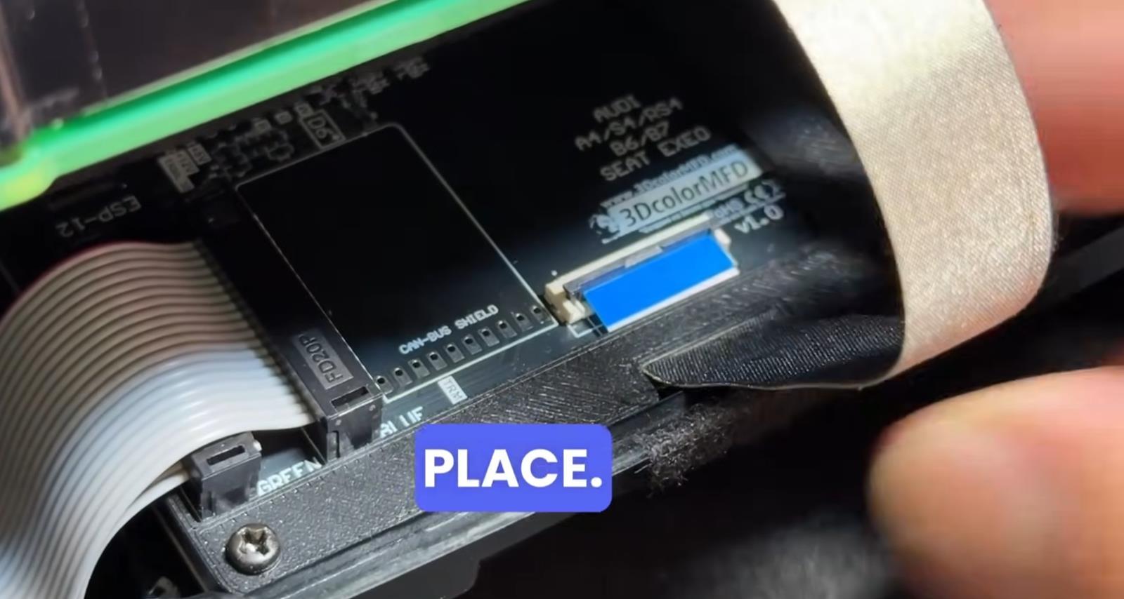
  1.5. Remove the display
Удалите дисплей


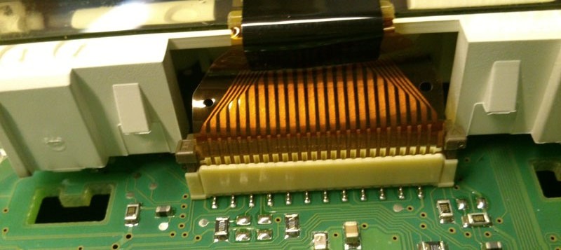
  1.5. Remove the display
Удалите дисплей
   
 
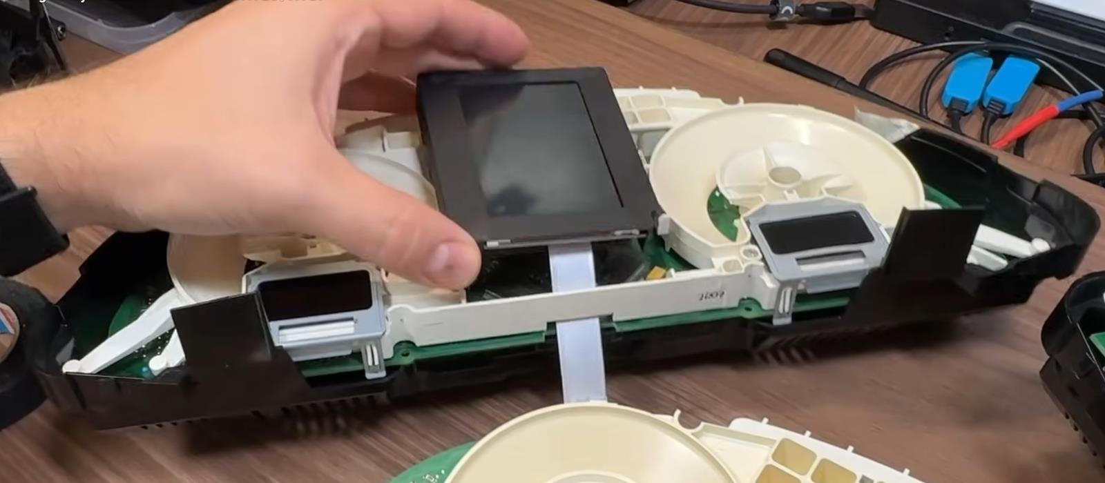
  1.5. Remove the display
Удалите дисплей


Important! / Важно!

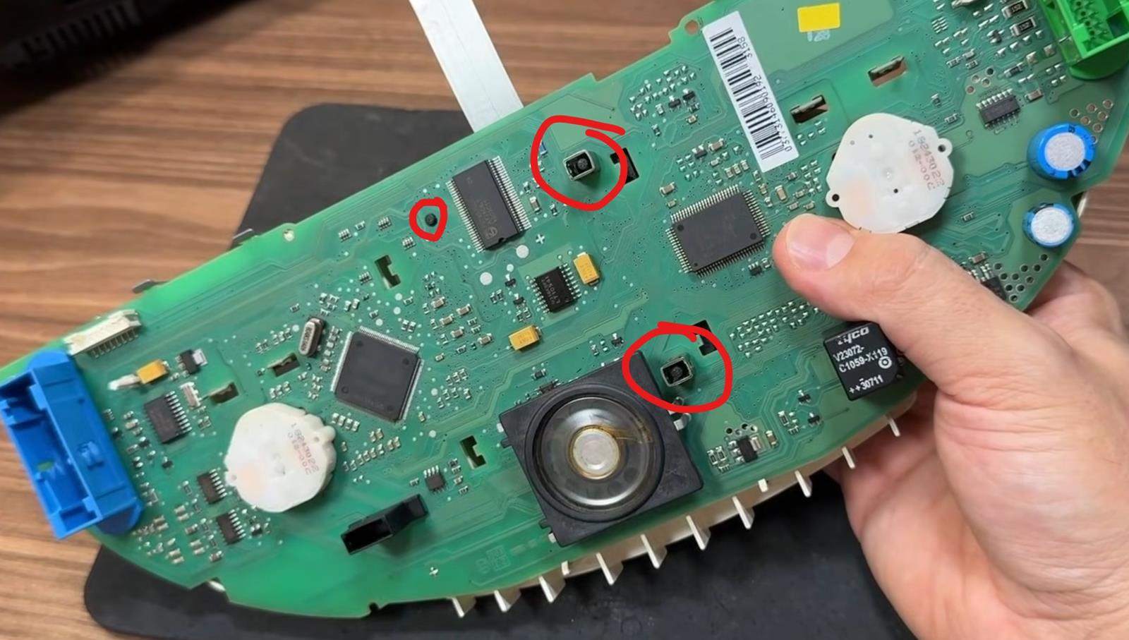
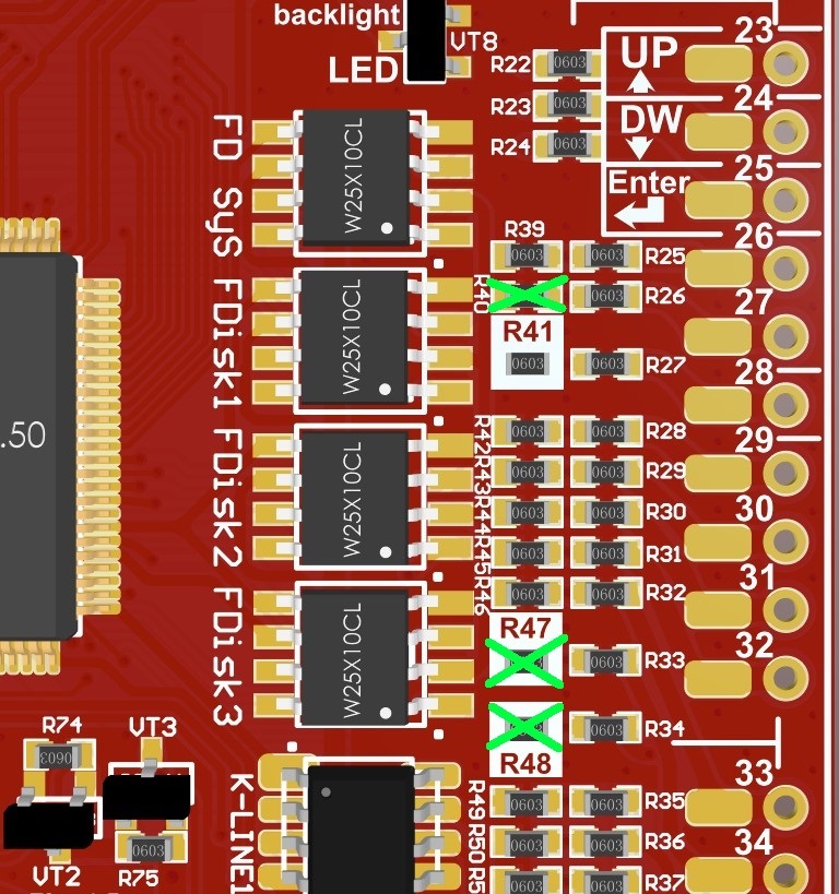
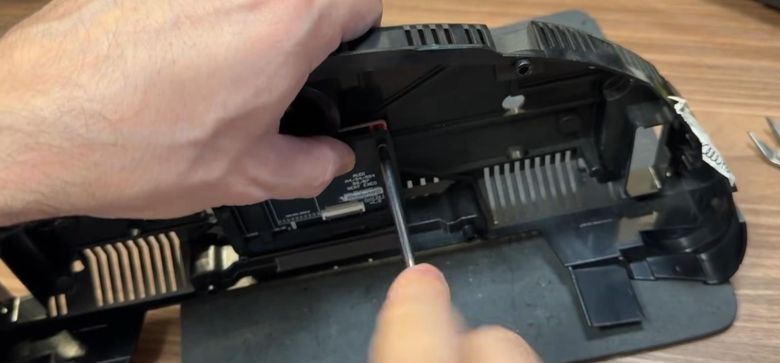
2.2 For proper operation of 3dMFD in your car model you need to remove resistors R40, R47, R48.

2.2 Для правильной работы 3dMFD в случае с вашей моделью авто нужно удалить резисторы R40, R47.

 
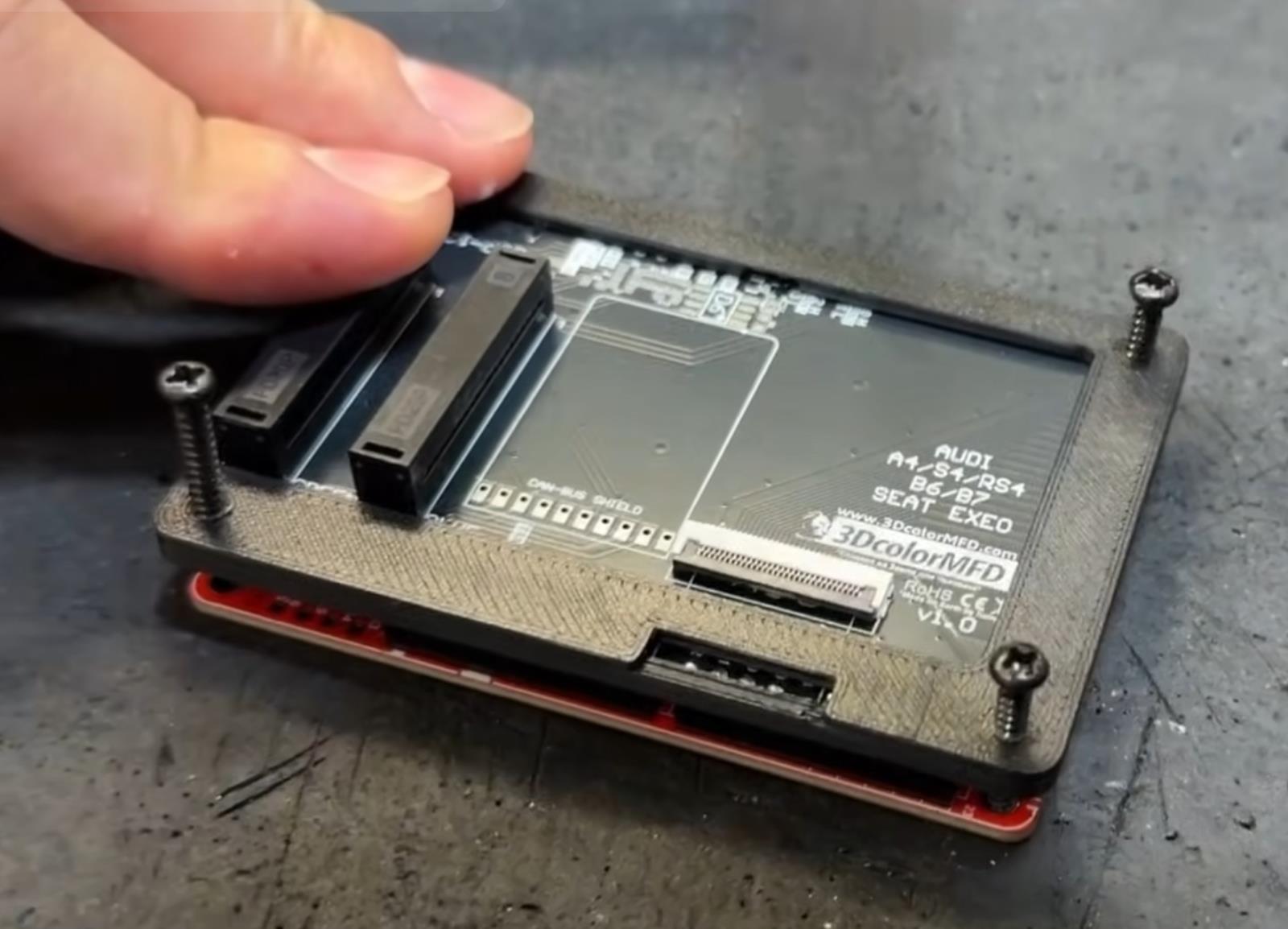
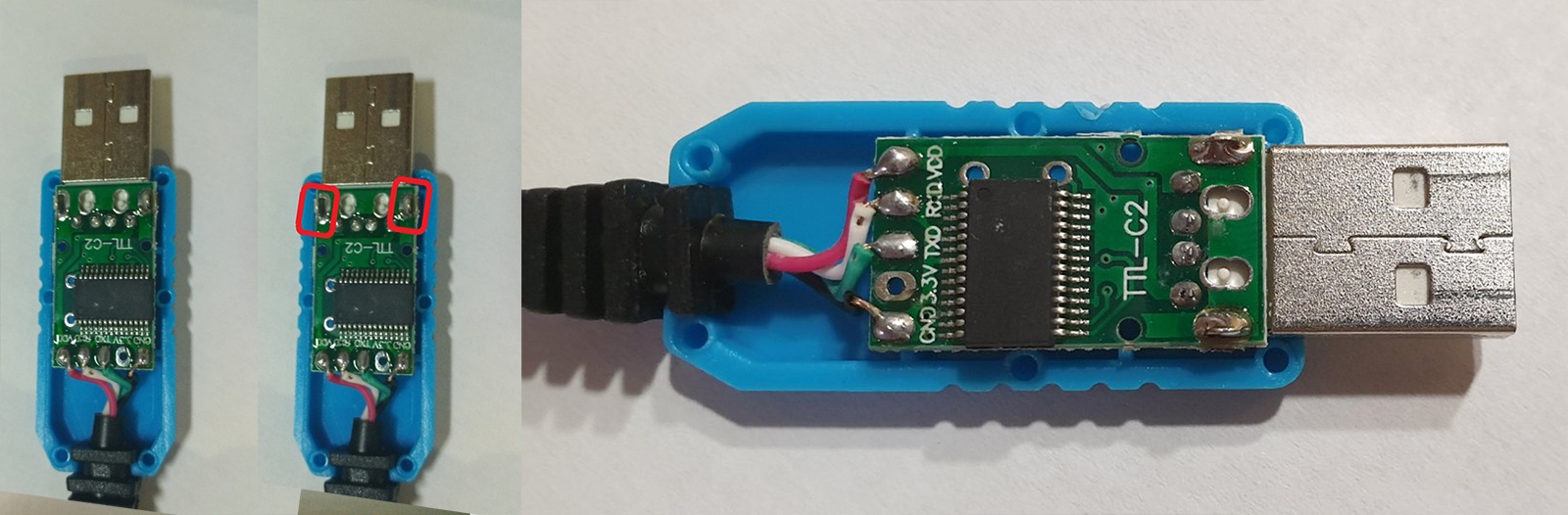
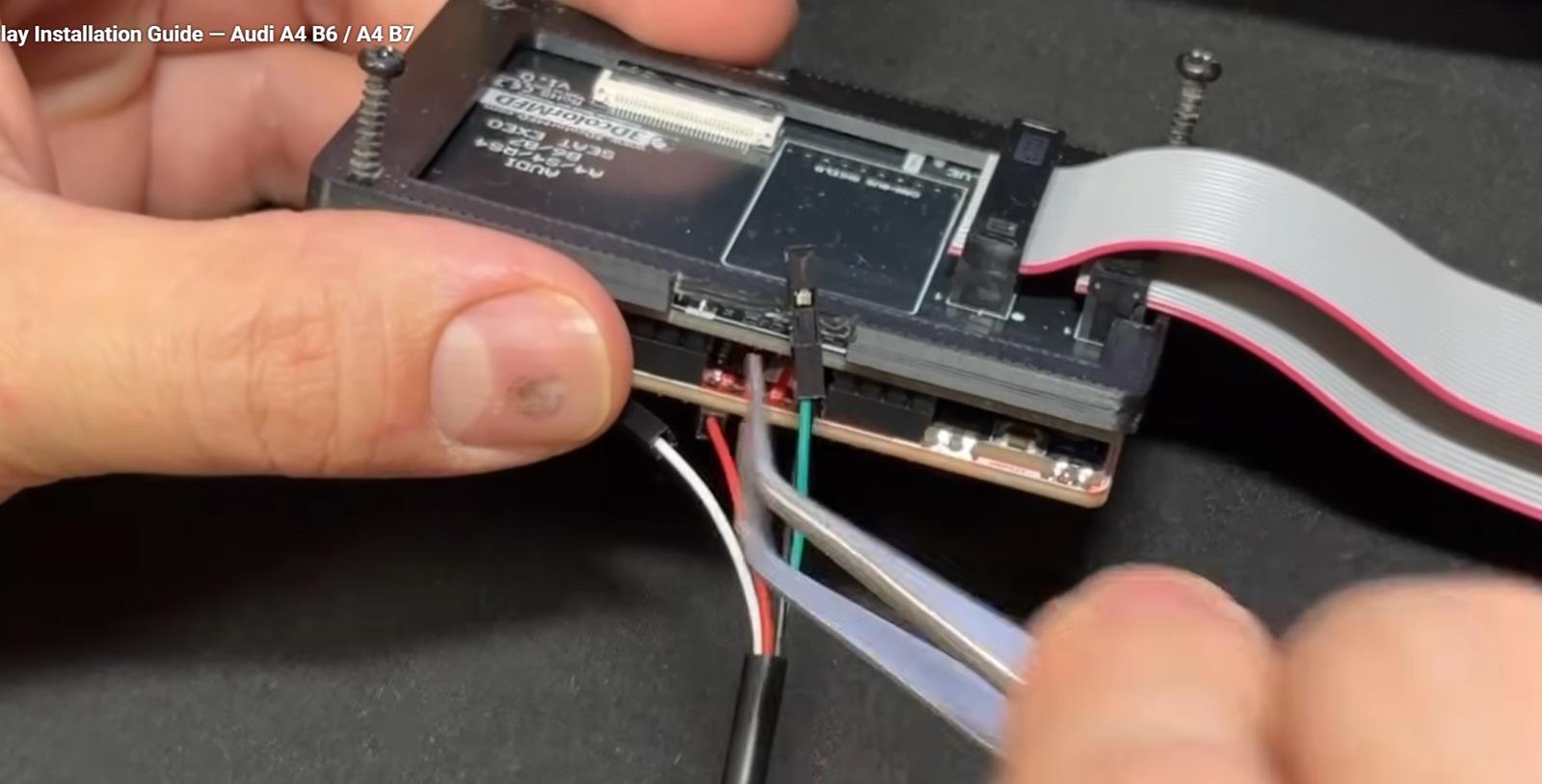
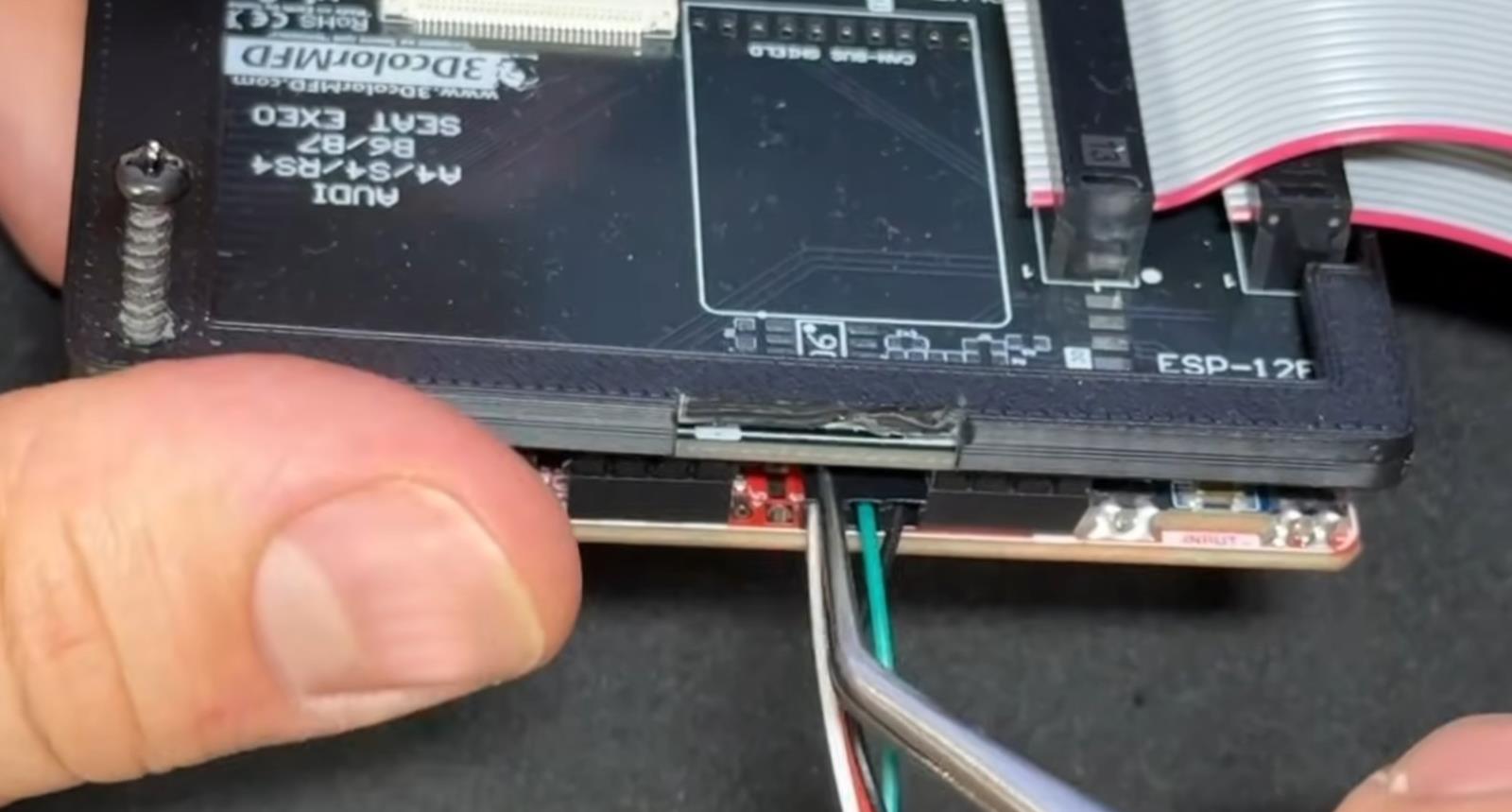
  4.1. BETTER USB connection option, you must solder the wires to the board.


4.1. Предпочтительный вариант подключения USB, вы должны припаять провода к плате.

4.1.Acceptable USB connection option, you can use the connector.


4.1. Допустимый вариант подключения USB, вы можете использовать разъем для подключения.


  4.2. OpenUSB And solder the metal ears marked in red.


4.2. Откройте USB и припаивайте металлические уши отмеченные  красным


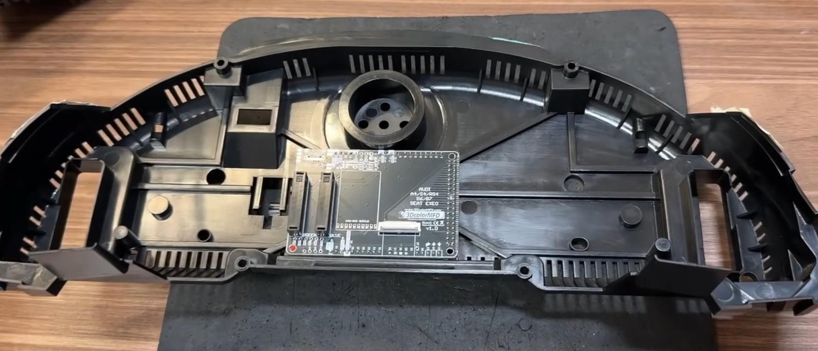
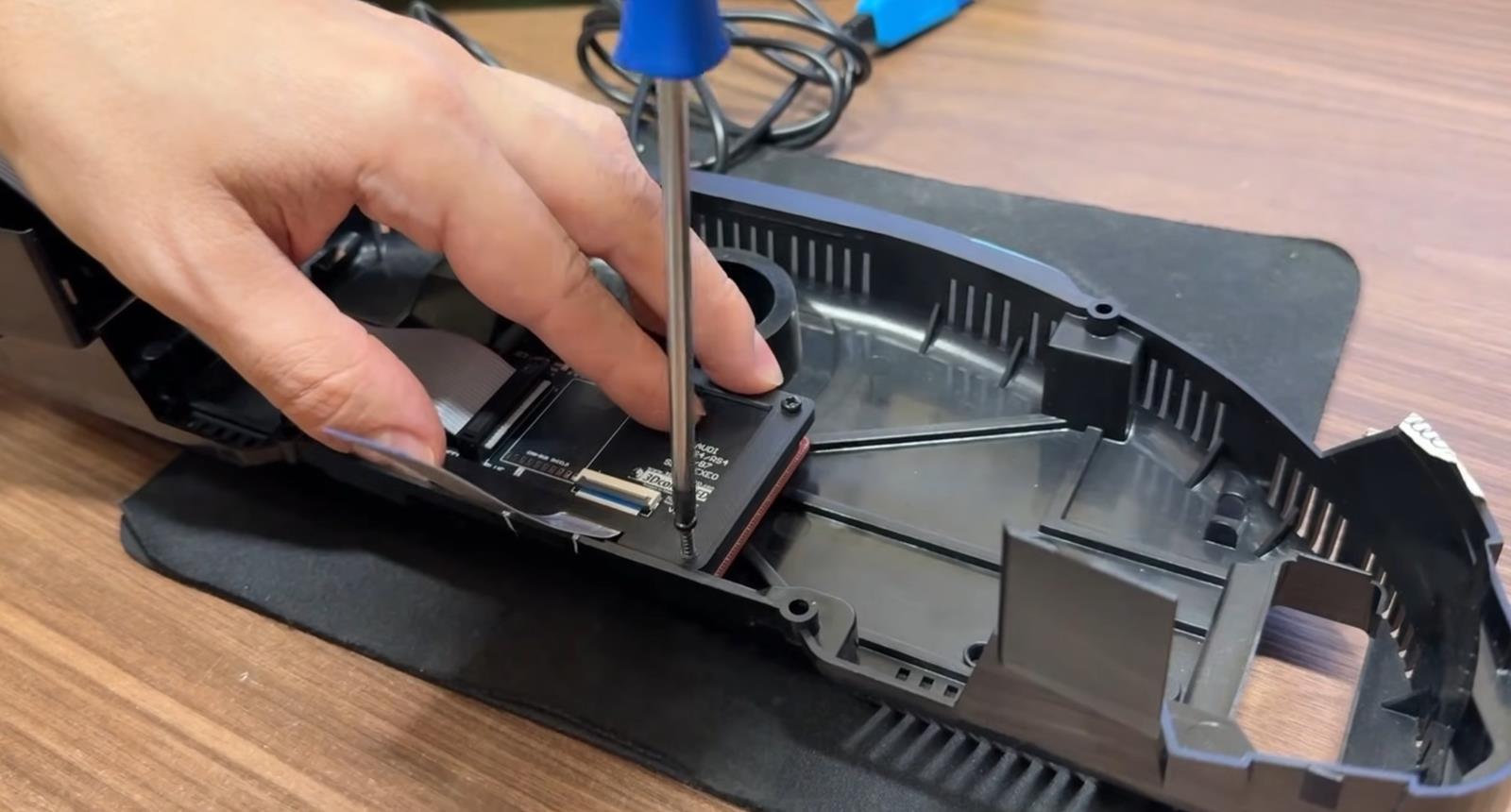
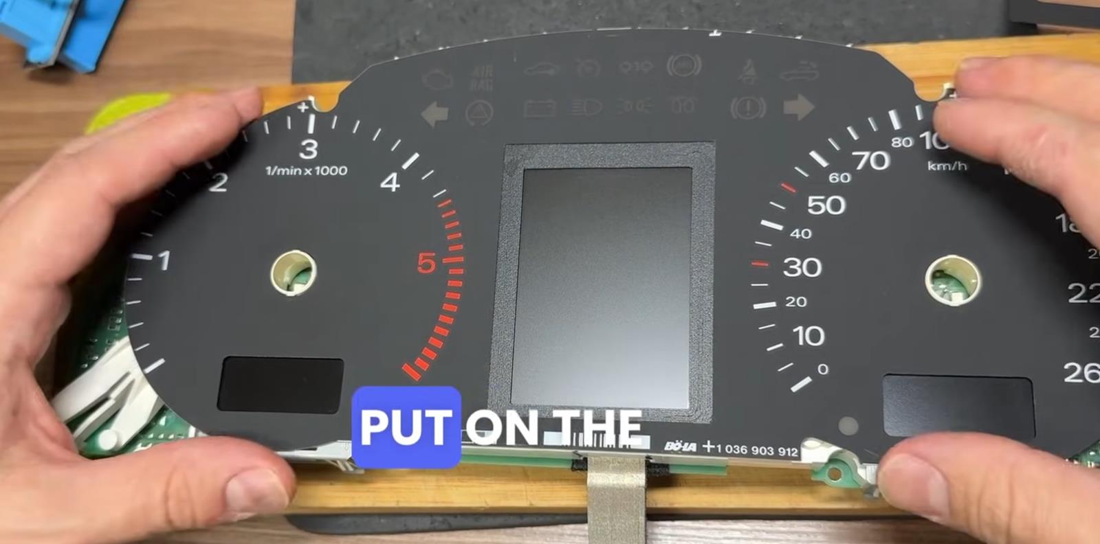
Attention! Be very careful when installing the dashboard cover!
Otherwise, you may damage the display!


Внимание! очень аккуратно устанавливайте маску приборной панели!
В противном случае вы можете повредить дисплей!


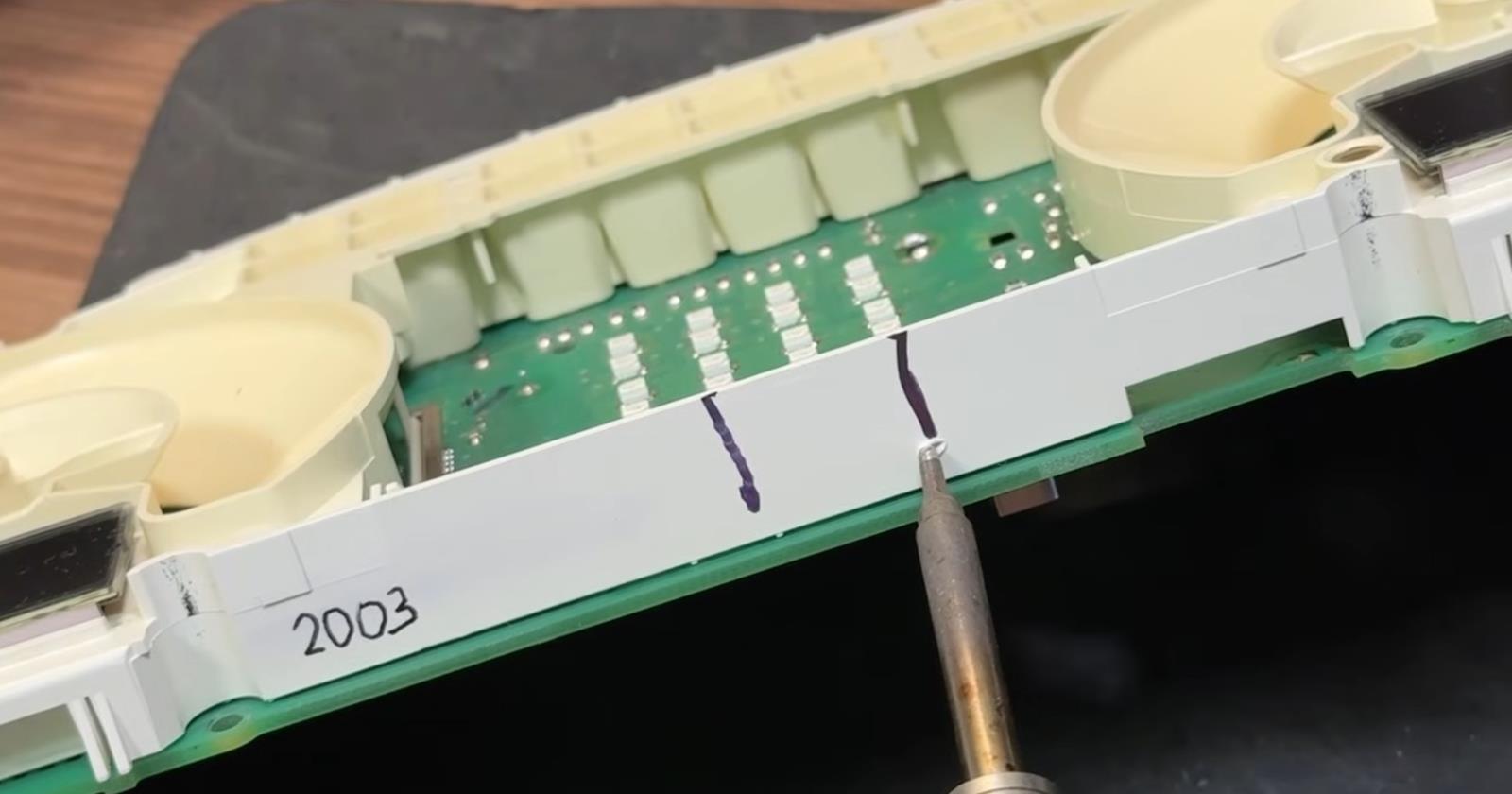
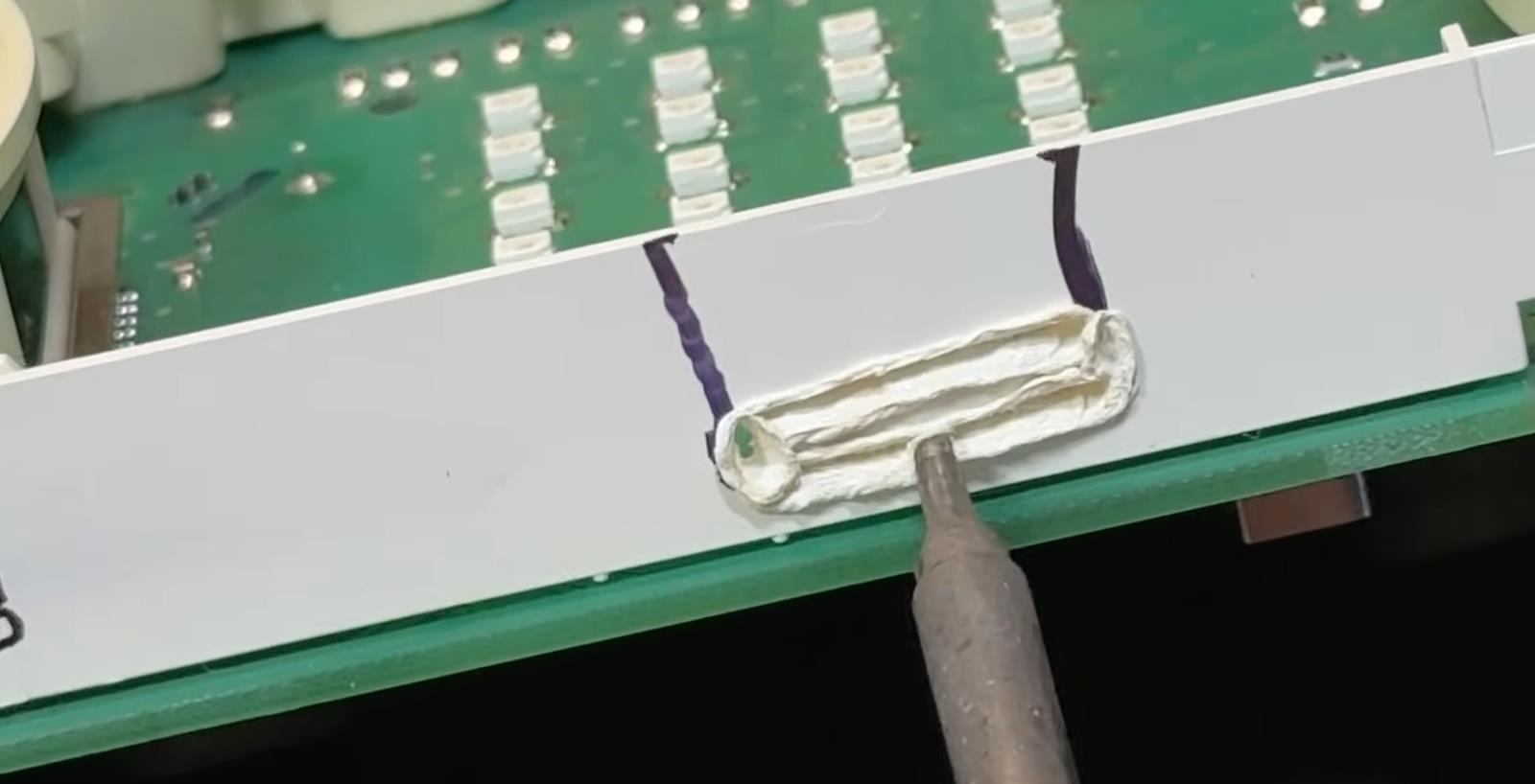
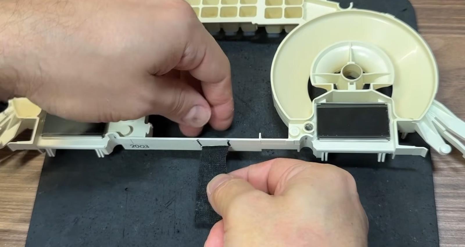
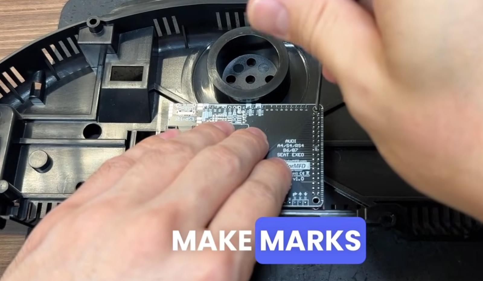
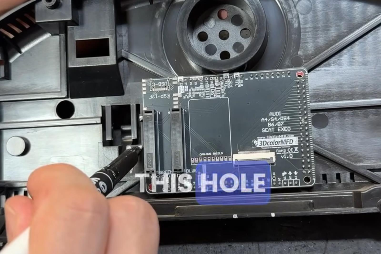
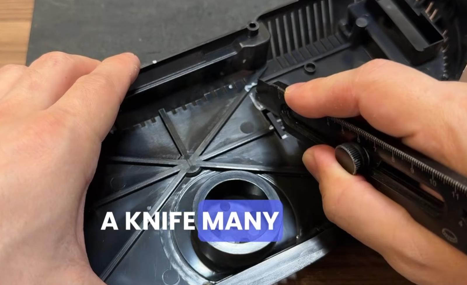
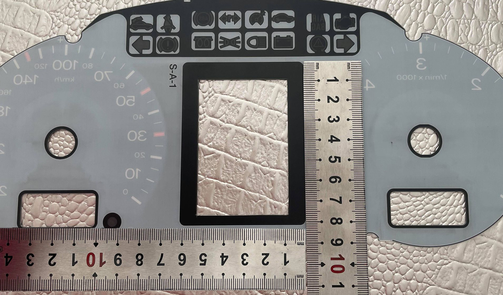
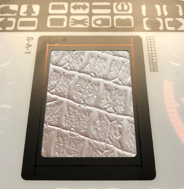
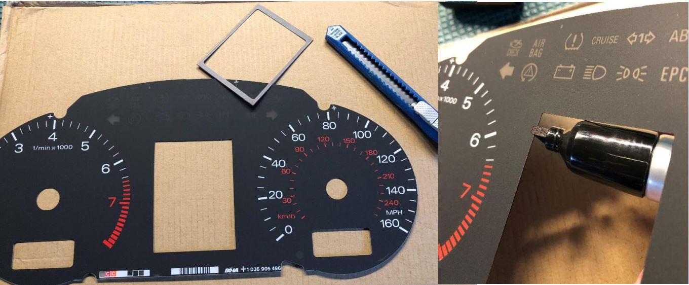
8.1.The screen window in the face must be enlarged. Cut 3mm on top, 4mm on bottom, and 1-2mm on each side.

The window will go from 41mmx61mm to 48mmx68mm.

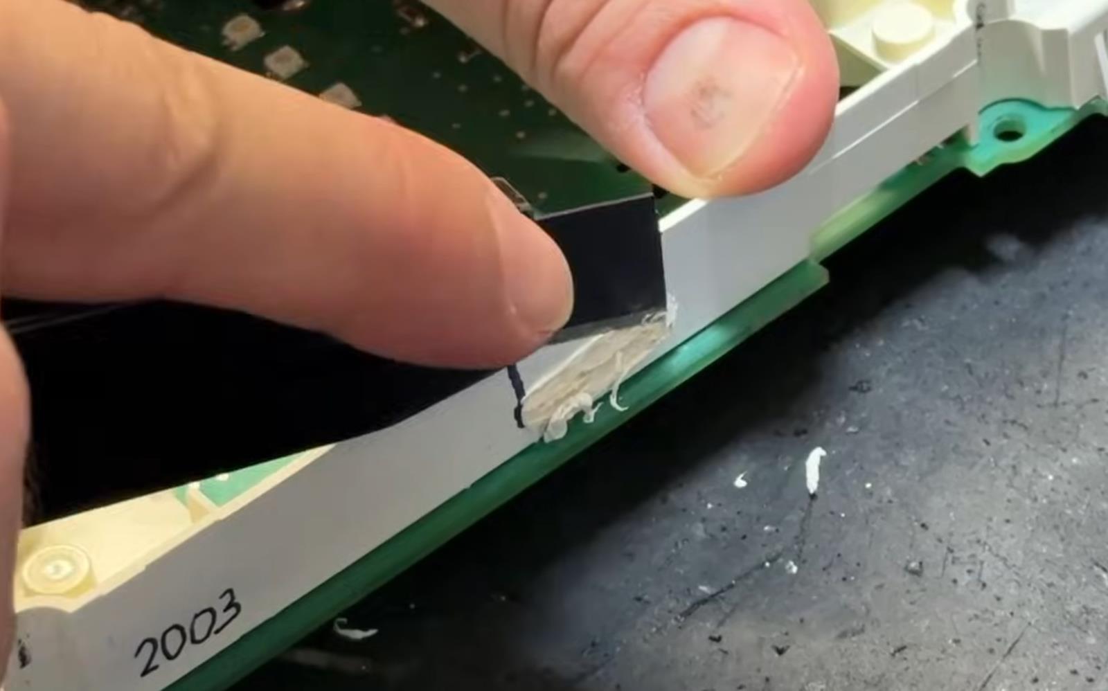
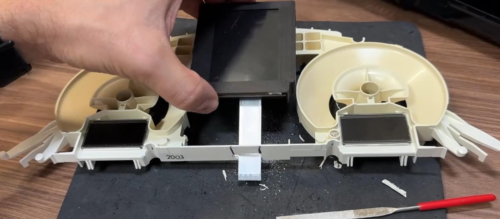
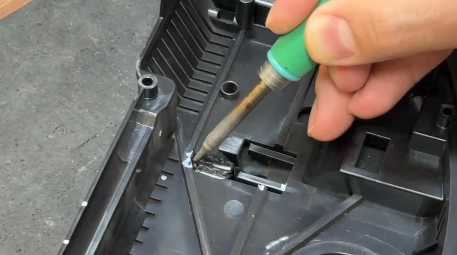
Use a flat edge and razor blade to score these marks until the plastic can be removed.

Make sure these cuts are straight and clean as this will be seen once the cluster is reassembled.

A black marker can be used to make the new edge look a little cleaner since the cut can expose “white” lines.


8.1. Окно для экрана можно увеличить. Отверстие должно быть расширено примерно на 3 мм сверху, на 4 мм снизу.
снизу и по 1-2 мм с каждой стороны. Проем увеличится с 41 мм x 61 мм до 48 мм x 68 мм. Используйте канцелярский нож,

чтобы резать пластик. Будте очень аккуратны, потому что неровности будут видны после сборки! Используйте черный маркер для
того чтобы убрать «белые» линии оголившегося пластика в месте пореза..


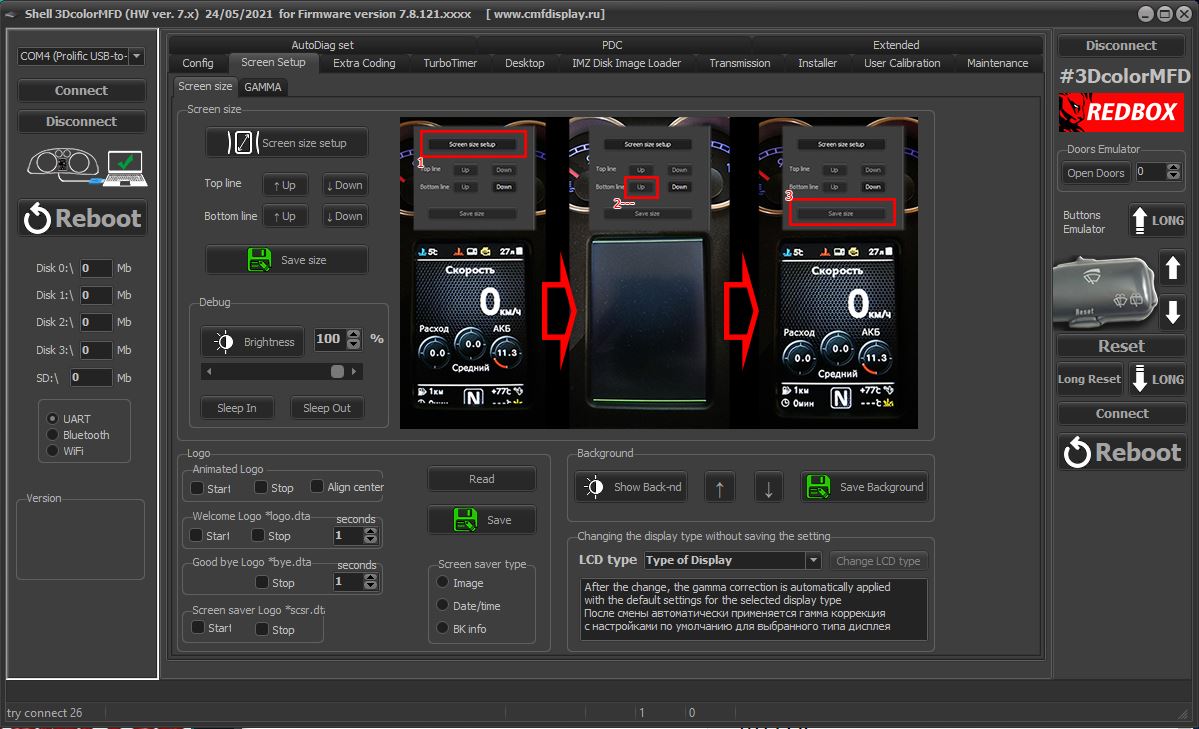
8.2.Using the Shell -> Screen Size program, adjust the display frames according to the window in the tidy scale.
 

8.2. С помощью программы Shell -> Screen Size настройте рамки дисплея по окну в шкале приборки.


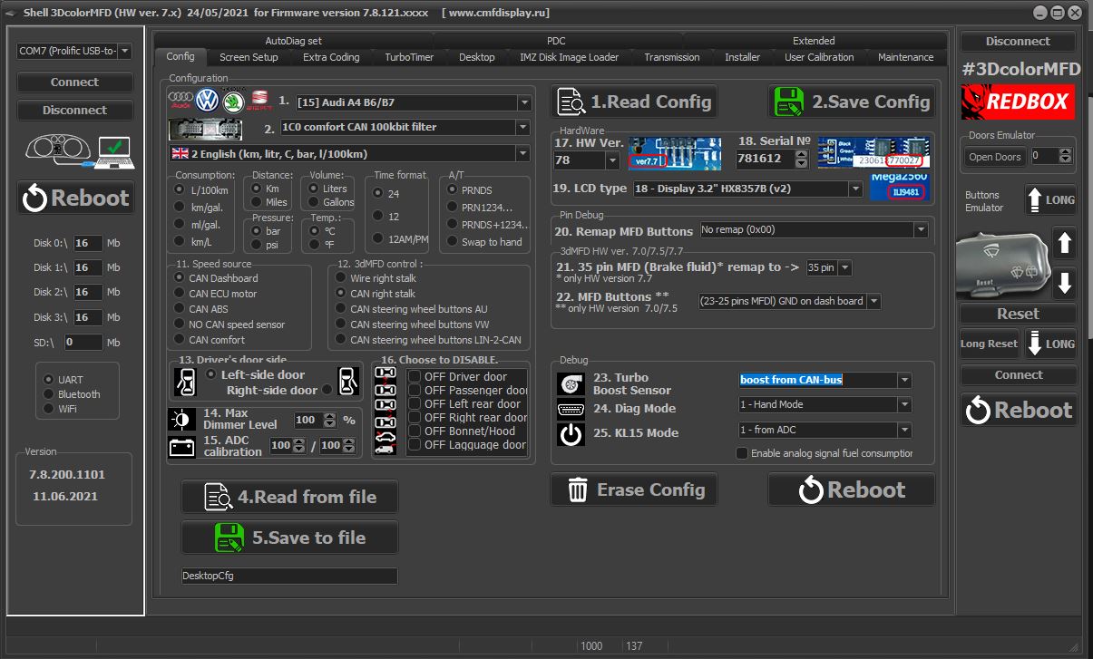
8. Some models of Audi A4 B6/B7 have data of boost pressure on can-bus. To do this, it is enough to make a setting in the Shell program: "boost from CAN-bus"
 

8. Некоторые модели Ауди А4 Б6/Б7 имеют данные о давлении наддува на can-bus. Для этого достаточно сделать настройку в программе Shell: "boost from CAN-bus"


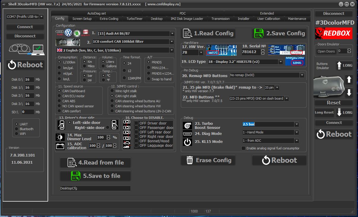
8. If this does not work, you need to lay a signal wire from the engine ECU to the cluster and then make a setting in the Shell program so that 3dMFD displays the turbo boost pressure.
 

8. Если это не работает вам нужно проложить сигнальный провод от ECU двигателя к приборке и затем сделать настройку в программе Shell, для того чтобы 3dMFD отображал давление наддува турбины.


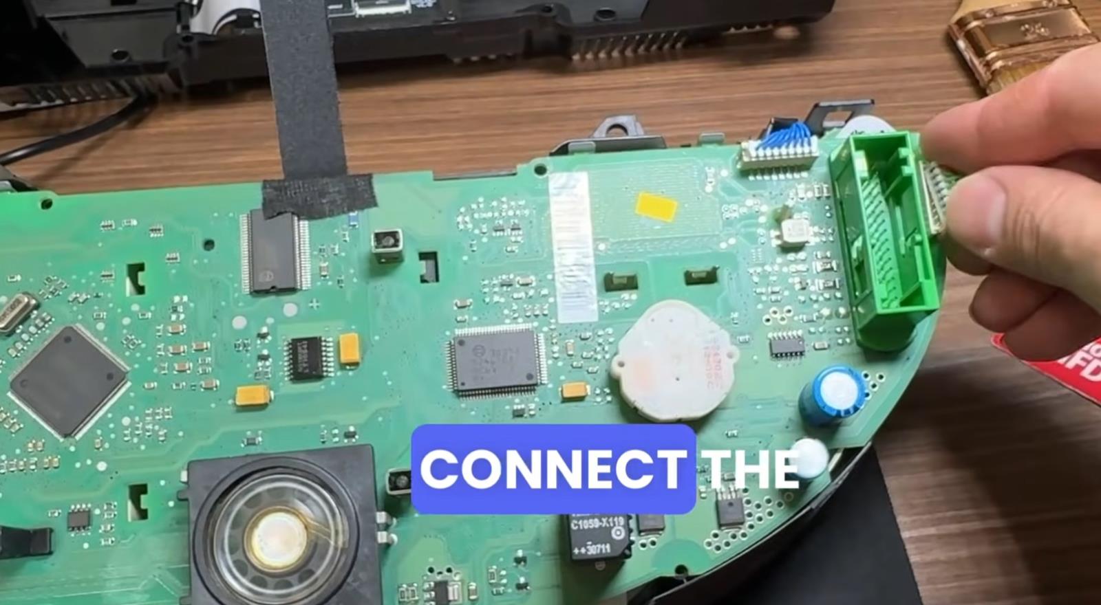
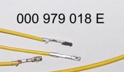
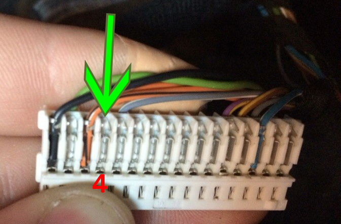
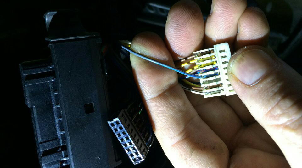
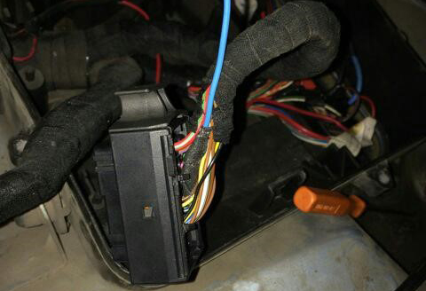
8.1. To connect the boost pressure control, you will need to add one PIN to the dashboard 4 pin green connector. The photo below is for example.


8.1. Чтобы подключить отображение давления наддува, вам нужно будет добавить провод от ЭБУд к 4-му PIN зеленого разъема приборки. Фото ниже приведено для примера.


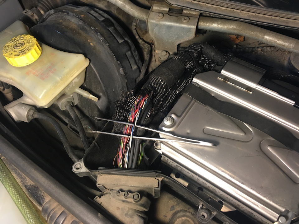
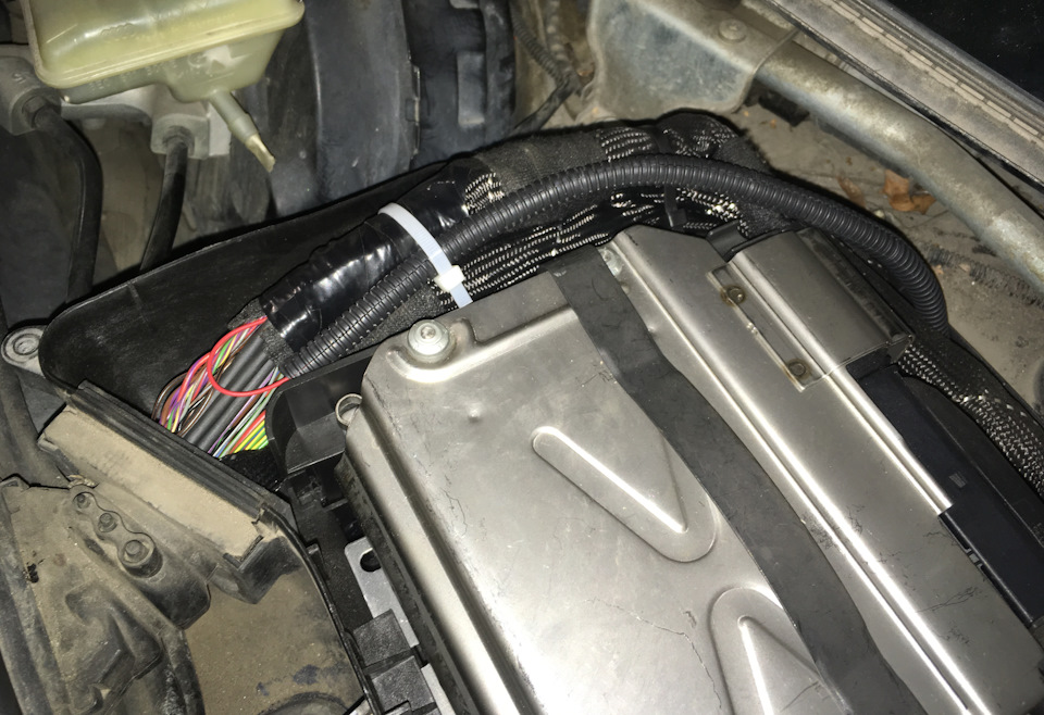
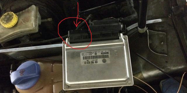
8.2. And the other end of the wire needs to connect the signal wire of the boost sensor to the engine ECU.
In order to determine the desired wire, you need to measure the voltage on this wire at idle, it should be 1.6V, (for a gasoline engine) and 1.9V (for a diesel engine) with an increase RPM, the voltage should increase.
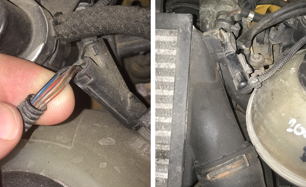
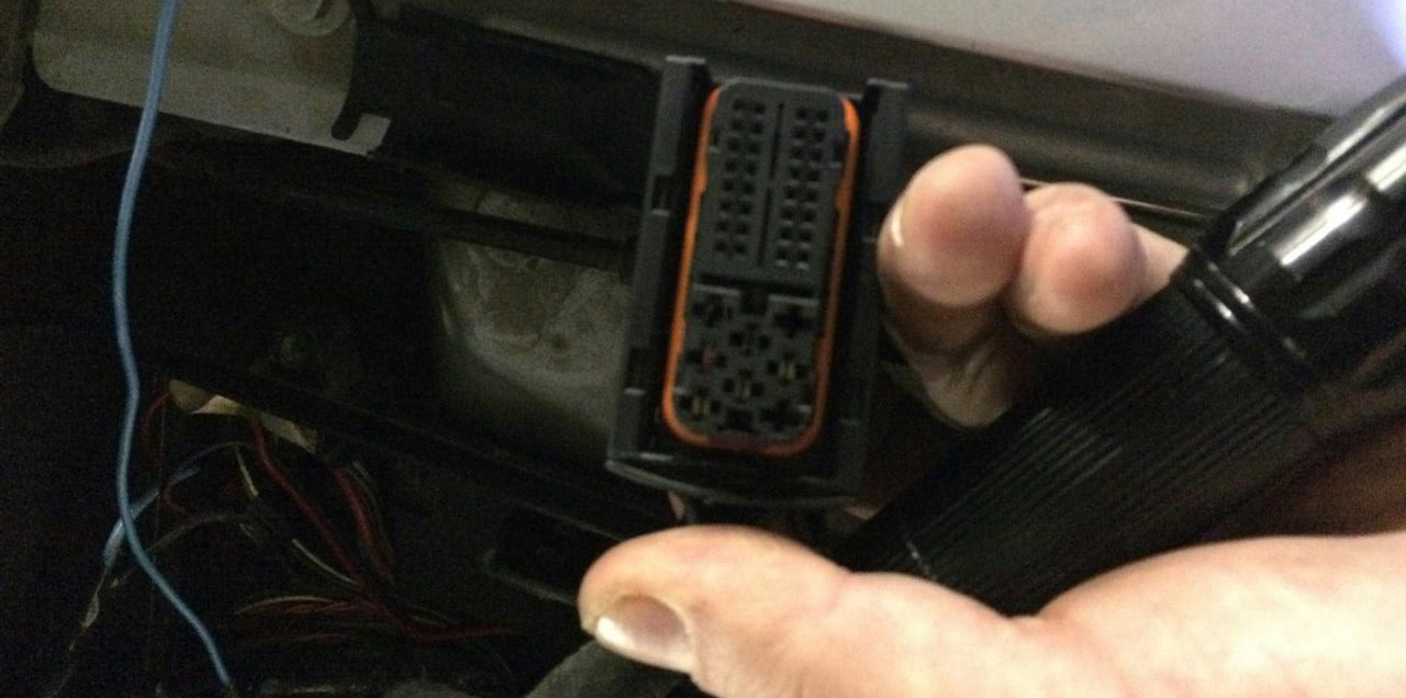
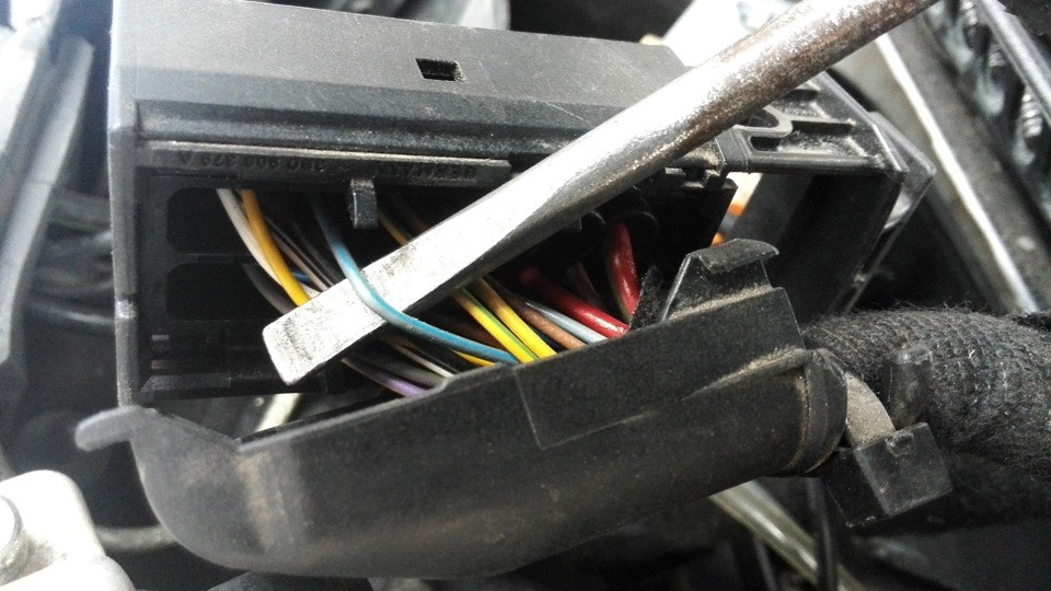
If your motor is not in the table, find the boost sensor under the hood, it has 4 wires, use a multimeter to determine the signal wire, remember its color and find this wire in the ECU connector, or call it with a multimeter.


8.2. А второй конец провода нужно подключить сигнальный провод датчика наддува в ЭБУдвигателя.
Для того чтобы определить нужный провод, нужно измерить
на этом проводе на холостом ходу напряжение, должно быть 1,6в,(для бензинового двигателя) и 1,9В (для дизеля) с увеличением оборотов двигателя напряжение должно увеличиваться.
Если вашего мотора нет в таблице, найдите под капотом датчик наддува, у него 4 провода, с помощью мультиметра определите сигнальный провод, запомните его цвет и найдите этот провод в разъеме ЭБУд, или прозвоните с помощью мультиметра.


(Алексей) https://www.drive2.ru/l/529786209900167450/


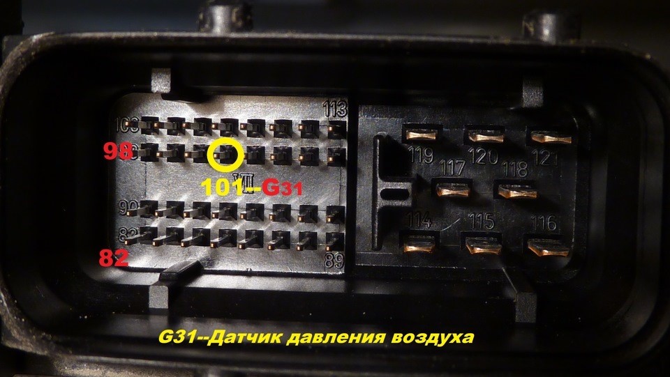
8.3. Usually it is blue - gray wire (blue with a gray bar) to the incoming on the 101st contact of a smaller brain connector. (for a gasoline engine)

On diesel engines (AVB and others): 
- 71st contact of the motor brain, green - red Wire (green with a red stripe).

On petrol (AWM and others): 
- 101st contact of the motor brain, gray - blue wire (gray with a blue stripe).

In general, as far as I understand, at all B5-x diesel 1.9T supercharging is connected to the 71st and the gasoline 1.8T is connected to the 101st contact. The color of the wire can vary depending on the year / engine.


8.3. Чаще всего со стороны ЭБУД к сине-серому проводу (синий с серой полосой) приходящему

на 101-й контакт меньшего разъема мозга.

На дизелях (AVB и других):
— 
71-й контакт
 моторного мозга, зелено-красный провод (зеленый с красной полосой).

На бензиновых (AWM и других):
— 
101-й контакт моторного мозга, серо-синий провод (серый с синей полосой).

Отличаться может цвет провода в зависимости от года/двигателя.


BES 2.7T T121 101 pin

blue-gray

  AJM 1.9TD T121 71 pin

yellow-black

AKN 2.5TD T121 71 pin

yellow-red

  AUY 1.9TD T121 71 pin

yellow-black

BQW 2.0TD T94 78 pin

green-red

  AWT 1.8T T121 101 pin

blue-gray

AVG 1.9TD T80 40 pin

yellow-green

  AWM 1.8T T121 101 pin

blue-gray

AFN 1.9TD T121 70 pin

green-red

  AWD 1.8T T121 101 pin

blue-gray

AVB 1.9TD T121 71 pin

green-red

  AWP 1.8T T121 101 pin

violet-gray

AVF 1.9TD T121 71 pin

green-red

  AUM 1.8T T121 101 pin

violet-gray

AWX 1.9TD T121 71 pin

green-red

  AUQ 1.8T T121 101 pin

violet-gray

AHF 1.9TD T121 71 pin

yellow-black

  ARZ 1.8T T121 101 pin

violet-gray

ALH 1.9TD T121 71 pin

yellow-black

  ARX 1.8T T121 101 pin

violet-gray

ARL 1.9TD T121 71 pin

yellow-black

  ANB 1.8T T121 101 pin

blue-gray

ASV 1.9TD T121 71 pin

yellow-black

  APU 1.8T T121 101 pin

blue-gray

ASZ 1.9TD T121 71 pin

yellow-black

  APB 1.8T T121 101 pin

blue-gray

ATD 1.9TD T121 71 pin

yellow-black

  AMB 1.8T T121 101 pin

blue-gray

AXR 1.9TD T121 71 pin

yellow-black


9. And then we collect everything in the reverse order without forgetting to calibrate the needles with the help of the WAG-com.

9.1.       To do this, connect the device to the machine without installing the glass, connect the VAG-com,

9. СБОРКА
Собирайте все в обратном порядке, не забывая калибровать иглы с помощью программы VAG-com.

9.1 Для этого подключите кластер к автомобилю (без стекла) и подключите его с VAG-com.

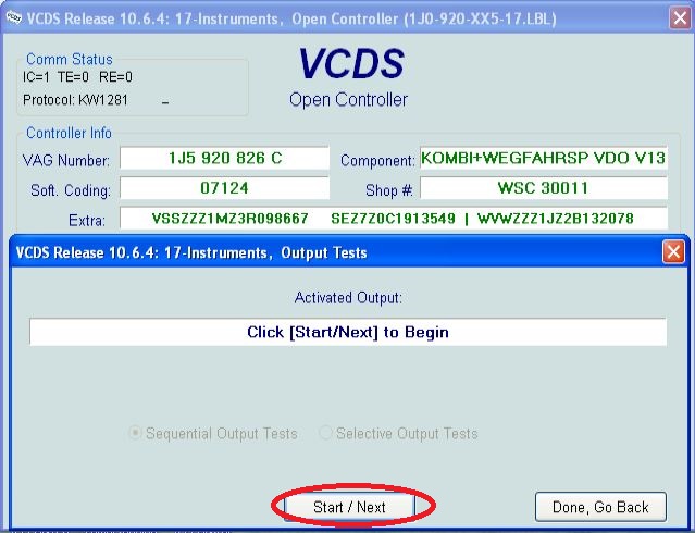
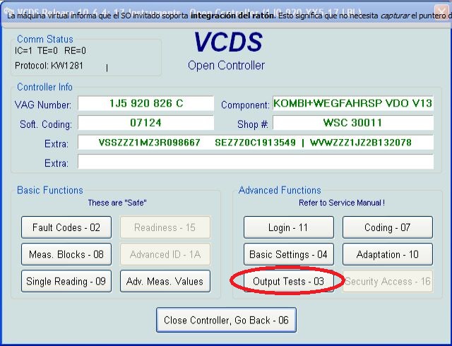
9.2.       Go into the 17-unit dash panel

9.2      Зайти в 17-блок панель приборов


9.3. Select test performers.

9.3. Выбрать тест исполнителей.


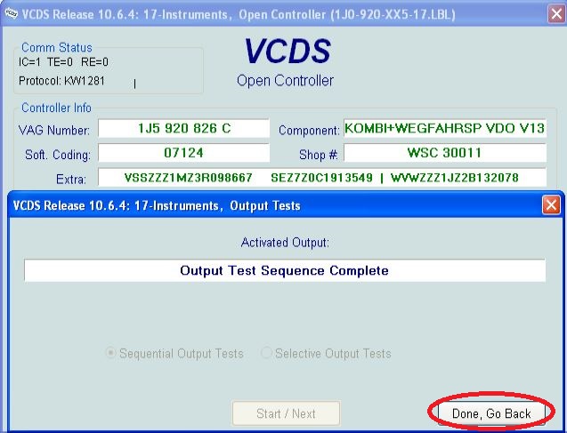
9.4. Choosing in turn a tachometer, temperature and the rest, the arrows in turn will be

Do a turn on the whole scale, and then freeze on:


6.4 Сделайте тест стрелок.
Выборайте по очереди: тахометр, температура охлаждающей жидкости, уровень топлива и скорость
Стрелки повернутся на всю шкалу, а затем сотановятся на контрольных точках.
Запомните или сделайте фотографию разницы в показания. Нажмите «Готово» и выйдите из блока. Выключите зажигание, выньте ключ и установите иглы в правильное положение, повернув их назад против часовой стрелки.


9.5. Tachometer - 3 thousand revolutions

9.5. Тахометр - на 3 тыс. оборотов

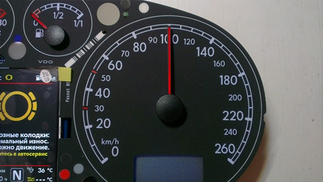
9.6. Pace. Coolant - middle

9.6. Спидометр - на 100 км/ч


9.7. Fuel level - middle

9.7. Уровень температуры ОЖ - по средине

9.8. Speedometer - at 100 km / h

9.8. Уровень топлива - по средине


Then check everything again
You can not turn the needles too quickly correcting the position, you can damage the motors of the needles
You can not turn the needles, when there is power on the device.

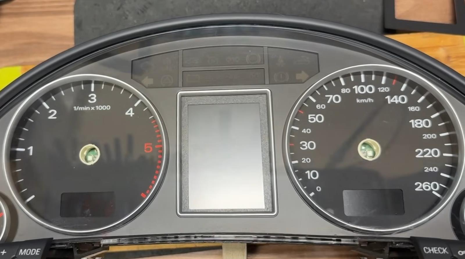
10.  Put back the cluster glass and put the cluster back into the car.


11. Take a photo and post it on all social networks.
Go to auto club meeting and brag to your friends.

12. Show it to your girlfriend/wife with words: «Look what a cool thing I bought for just 20 bucks! » =)


  Затем проверьте все снова
Вы не можете поворачивать стрелки слишком быстро, исправляя положение, вы можете повредить двигатели стрелки, а так же нельзя поворачивать стрелки при включенной приборке.


10.  Поставьте обратно стекло кластера и вставьте кластер обратно в автомобиль.


11. Сфотографируйте и разместите его во всех социальных сетях. Отправляйтесь на встречу автоклуба и хвастайся друзьям.


12. Покажите это своей девушке / жене со словами: "Посмотри, какую классную вещь я купил всего за 20 баксов!" :)))


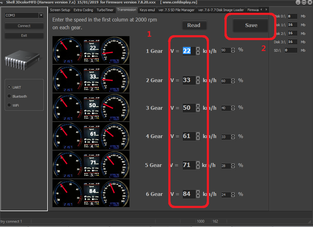
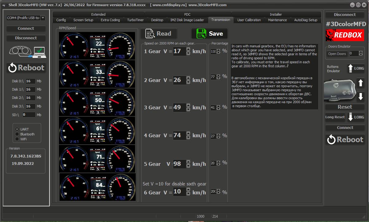
In cars with manual gearbox, the ECU has no information about which gear you have selected, and 3dMFD cannot read it,
so 3dMFD shows the selected gear in terms of the ratio of driving speed to RPM.
To calibrate, you must enter the travel speed in each gear at 2000 RPM in the first column.
Also, 3dmfd does not mean that neutral gear is engaged.
Only when you press the clutch pedal does the N signal appear.

 
  В автомобилях с механической коробкой передач ЭБУ двигателя не имеет информации о том, какую передачу вы выбрали,
и 3dMFD не может ее прочитать, поэтому 3dMFD показывает выбранную передачу по соотношению скорости движения и оборотов двигателя в минуту.
Для калибровки необходимо ввести в первую колонку скорость движения на каждой передаче при 2000 об/мин.
Кроме того, 3dmfd не означает, что включена нейтральная передача.
Только при нажатии на педаль сцепления появляется сигнал N.


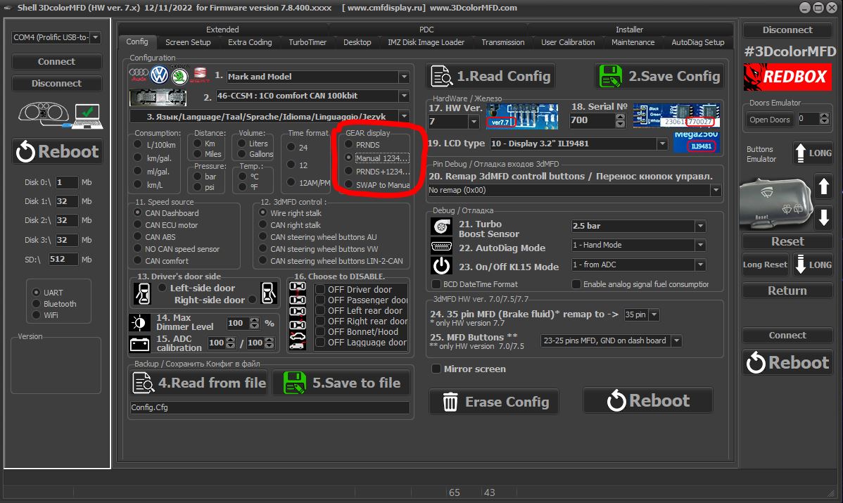
  If the N signal does not appear when the clutch pedal is depressed.
Check the settings in the Config tab


  Если при нажатии на педаль сцепления не появляется сигнал N.
проверте настройки во вкладке Конфиг


Audi A4 B7 disel 5 gears


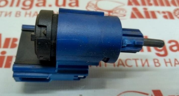
  If the settings in the Configure tab are correct, but the N signal does not appear when the clutch pedal is depressed.
Check if the clutch pedal micro switch is present and working.


  Если настройкf во вкладке Конфиг правильная, но при нажатии на педаль сцепления не появляется сигнал N.
Проверте наличие и работоспособность микровыключателся педали сцепления.