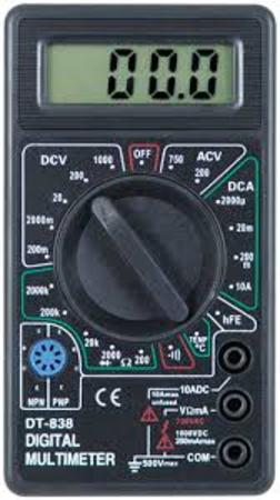
You will need:
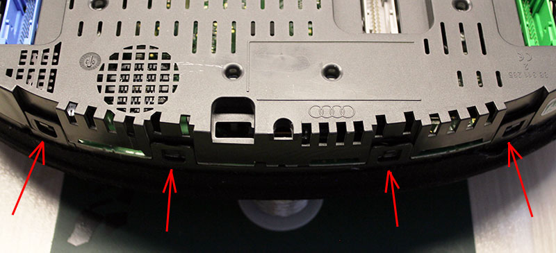
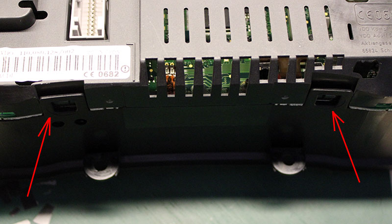
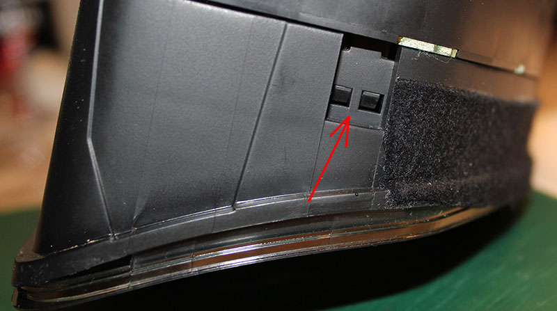
Bend all the latches and neatly remove the front of the case (with glass).
|
||||||||||||||||||||||||||||||||||||||||||||||||||||||||||||||||||||||||||||||||||||||||||||||||||||||||||||||||||||||||||||||||||||||||||||||||||||||||||||||||||||||||||||||||||||||||||||||||||||||||||||||||||||||||||||||||||||||||||||||||||||||||||||||||||||||||||||||||||||||||||||||||||||||||||||||||||||||||||||||||||||||||||||||||||||||||||||||||||||||||||||||||||||||||||||||||||||||||||||||||||||||||||||||||||||||||||||||||||||||||||||||||||||||||||||||||||||||||||||||||||||||||||||||||||||||||||||||||||||||||||||||||||||||||||||||||||||||||||||||||||||||||||||||||||||||||||||||||

|
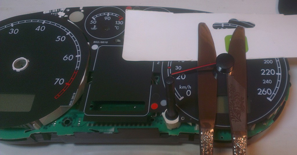
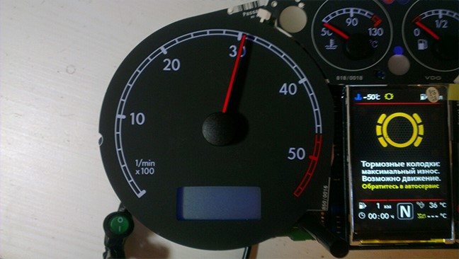
1.2 Remove the needles.
|
 |
|
|
1.2 Удалите
стрелки.
|
|
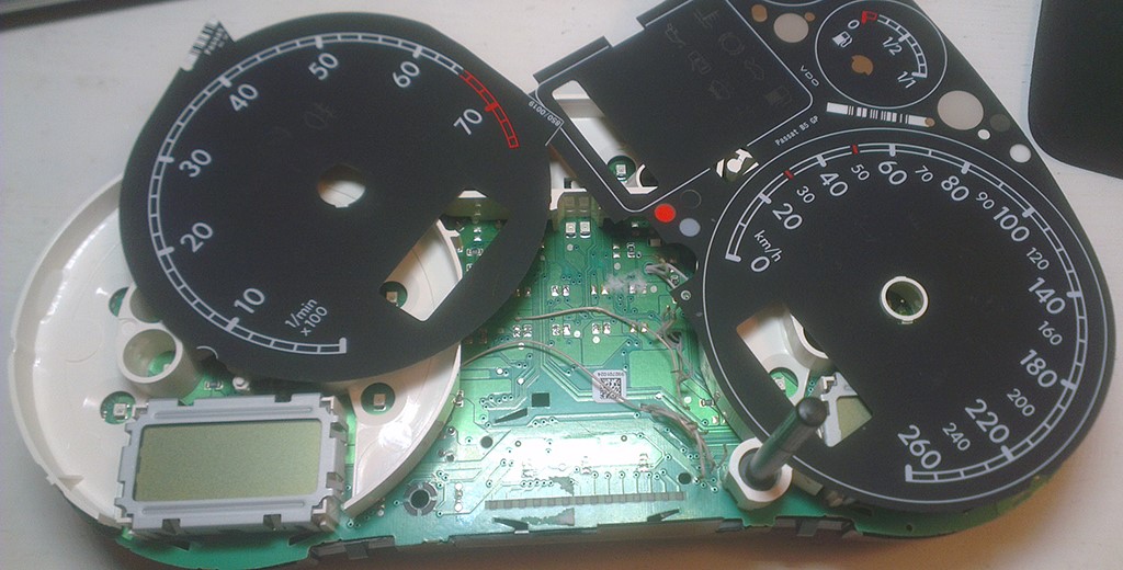
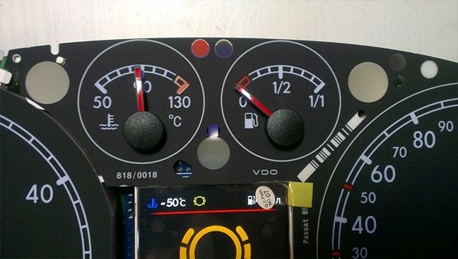
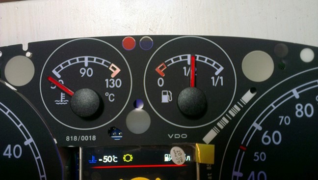
1.3. Then
remove the substrate. |
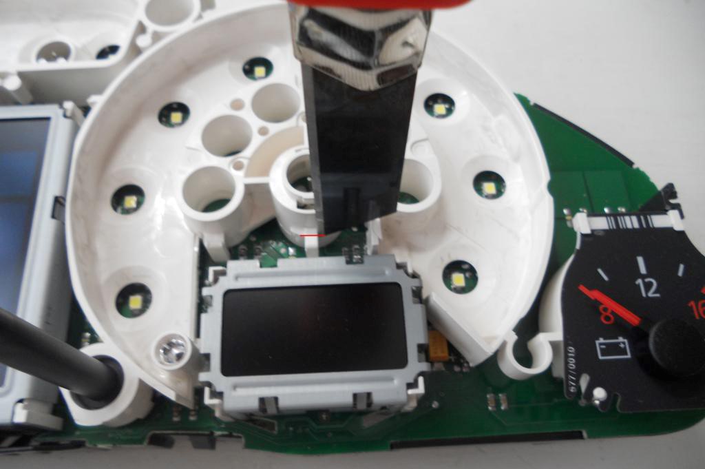
1.4.
Remove the small displays under the speedometer and tachometer and
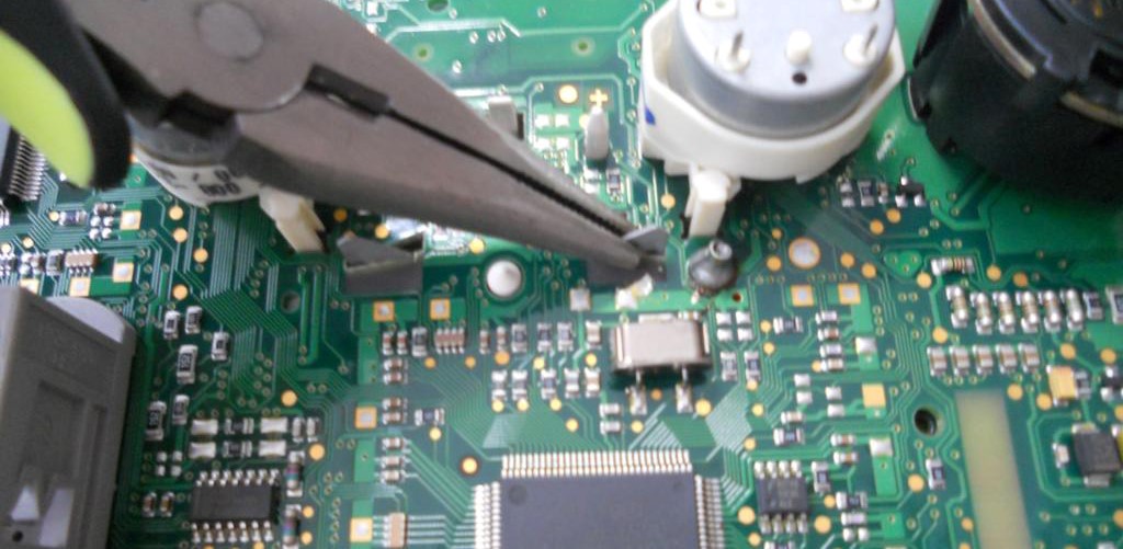
white plastic.Cut
the jumpers, we work carefully, so as not to damage the board. Удалите маленькие дисплеи и белый пластик рассеивателя. |
|
|
 |
|
1.4.1.
Remove
white plastic (noFIS) Удалите белый пластик
|
|
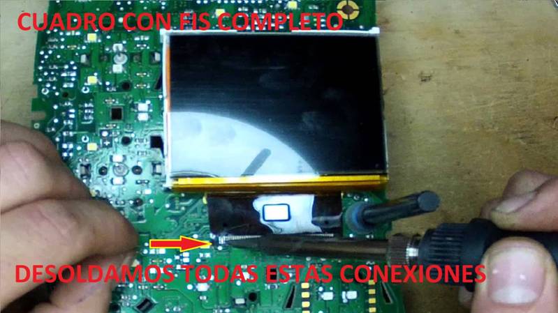
1.5.
Remove display (fullfFIS)
|
||
|
1.5.1.
Remove display (fullfFIS)
|
|
|
|
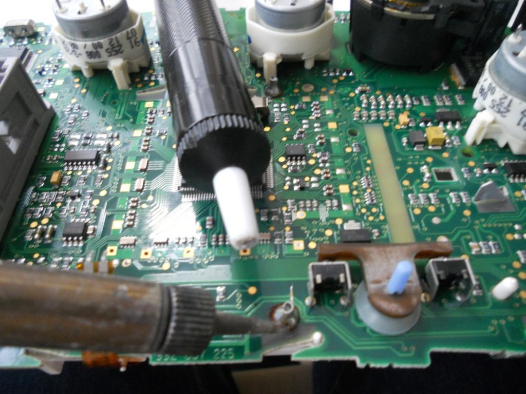
1.5.2. On some instrument panels, the plastic base of the
OEM FIS is soldered to the board pretty hard, to dismantle it — remove the tin, using a soldering iron and a special vacuum. На некоторых приборных панелях пластиковая основа OEM FIS припаяна к плате довольно туго, чтобы его разобрать — снять олово, при помощи паяльника и специального пылесоса. 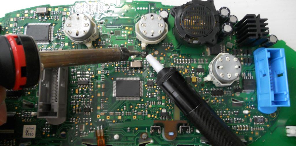 |
|
|
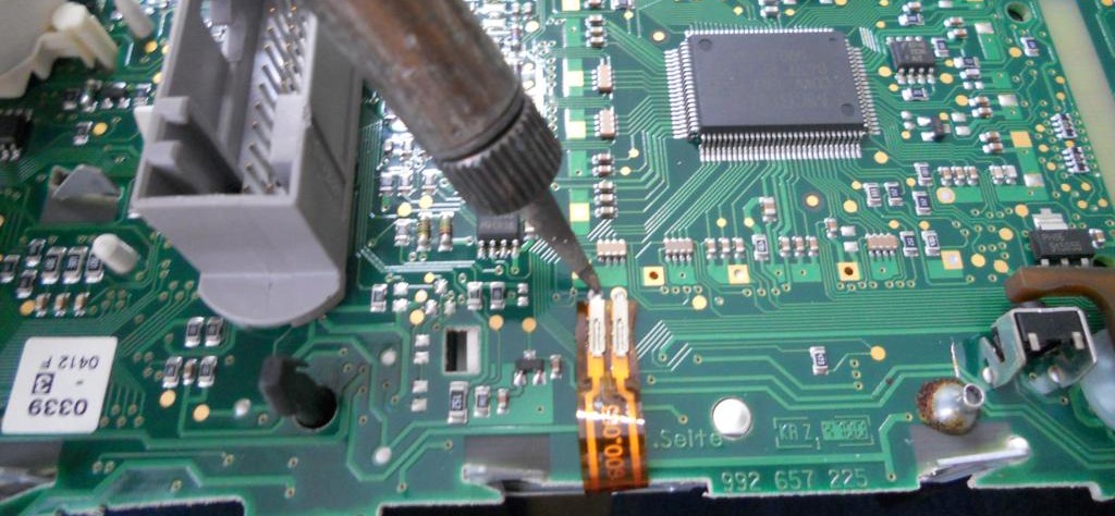
1.5.3. Remove temperature sensor. There is a temperature sensor in a fullFIS clusters. It can be removed with a soldering iron or simply cut off the sensor tape in any convenient place, so that it does not interfere later.
1.5.3. Удалите датчик температуры.
|
|
|
1.5.4. Remove the white display holder.
1.5.5. Снимаем белый
держатель дисплея.
|
|
|
|
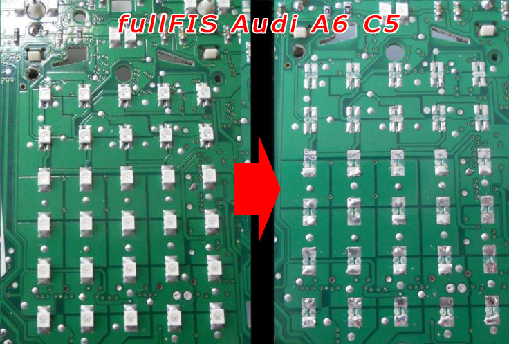
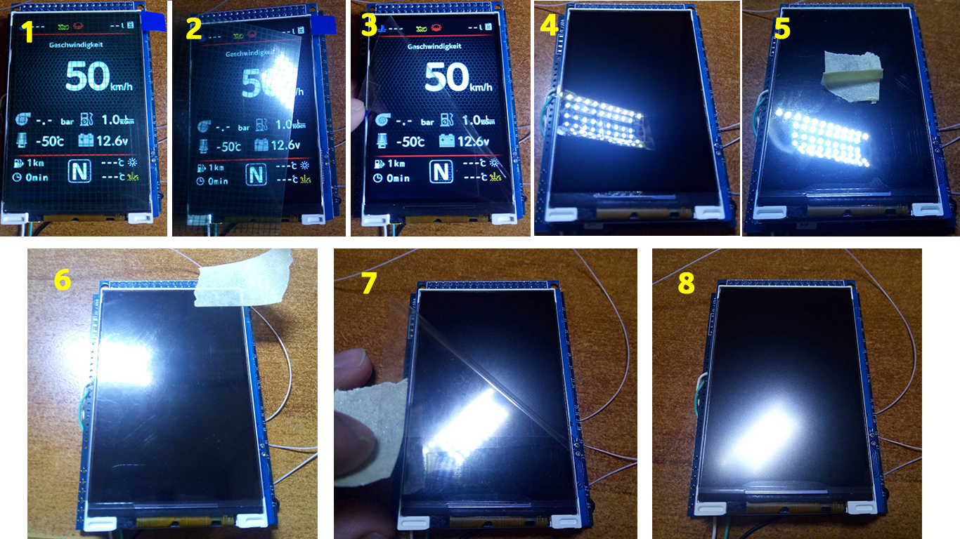
1.6. Then you need to remove all the LEDs that are were under the standard display
1.6.
Затем нужно убрать все светодиоды, которые были
|
|
|
|
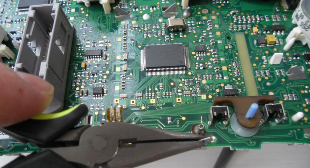
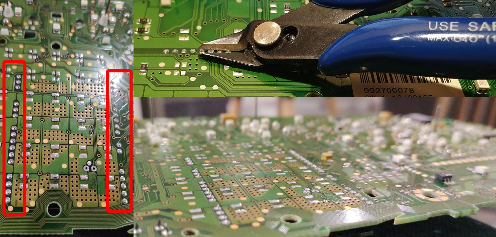
1.7. Remove all metal pins 1.7. Удалите металлические пины
|
|
|
|
1.8. We make sure
that there are no jumpers made of tin. 1.8. Следим за тем,
чтобы не было перемычек из олова и. |
|
|
1.9.
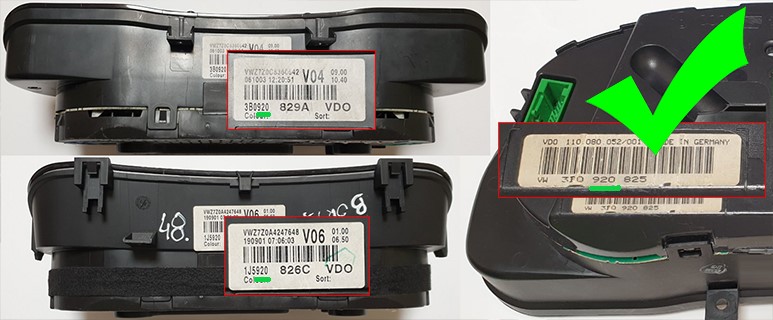
VERY IMPORTANT:
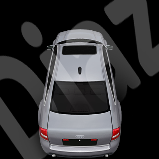
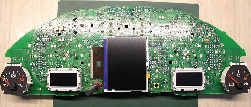
Below you can see photos of some clusters. |
1.9.
VERY IMPORTANT:
WAY 2
Below you can see photos of some clusters. |
|
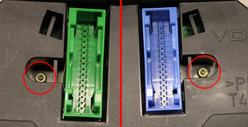
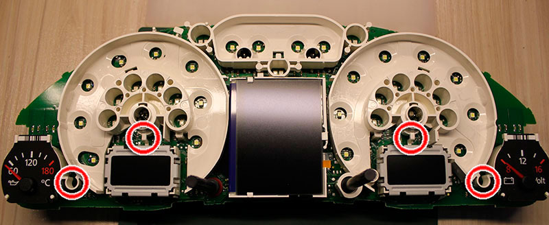
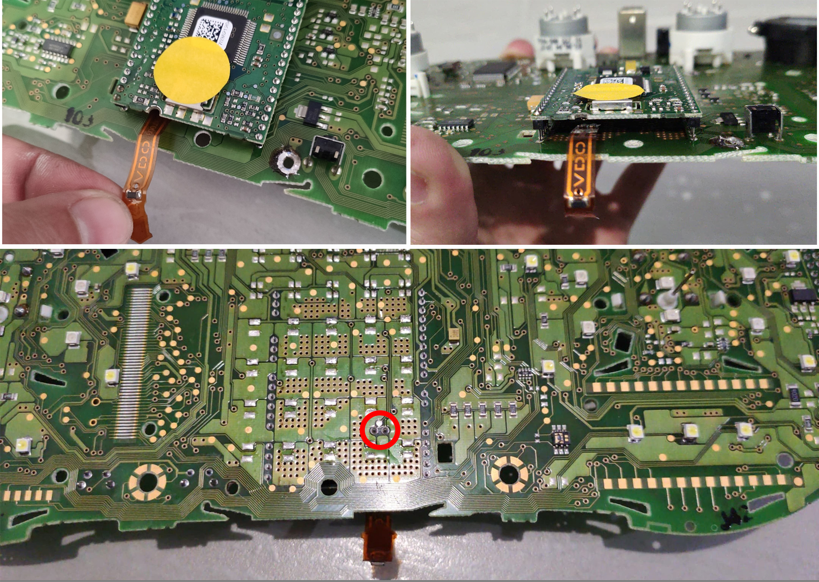
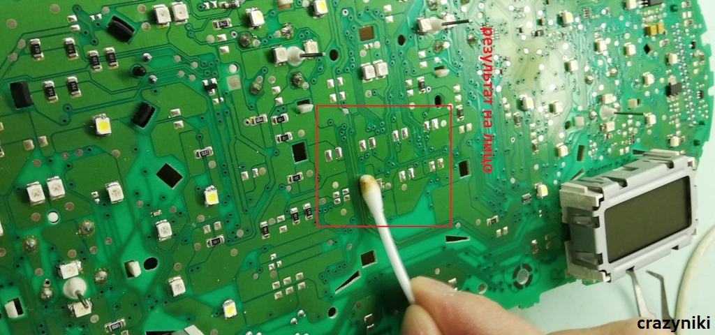
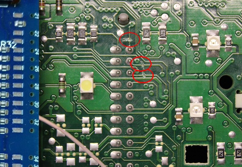
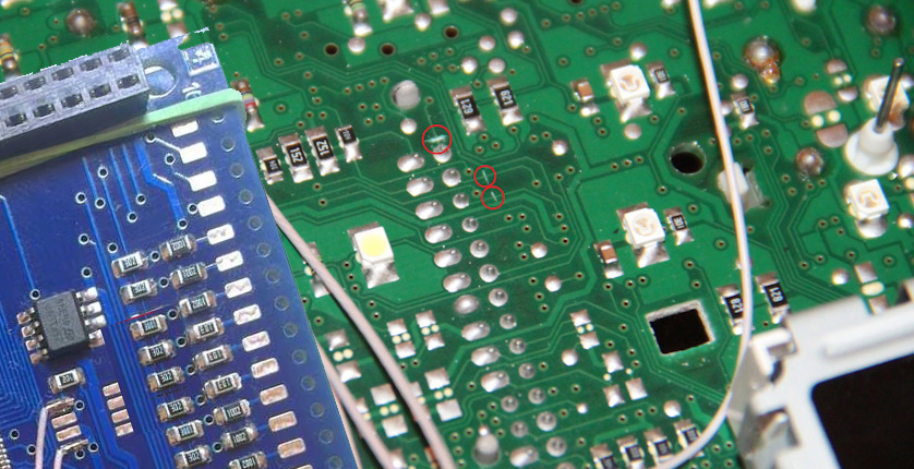
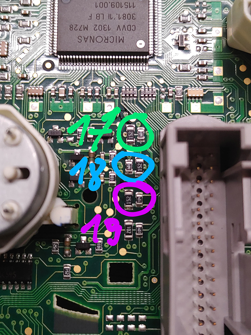
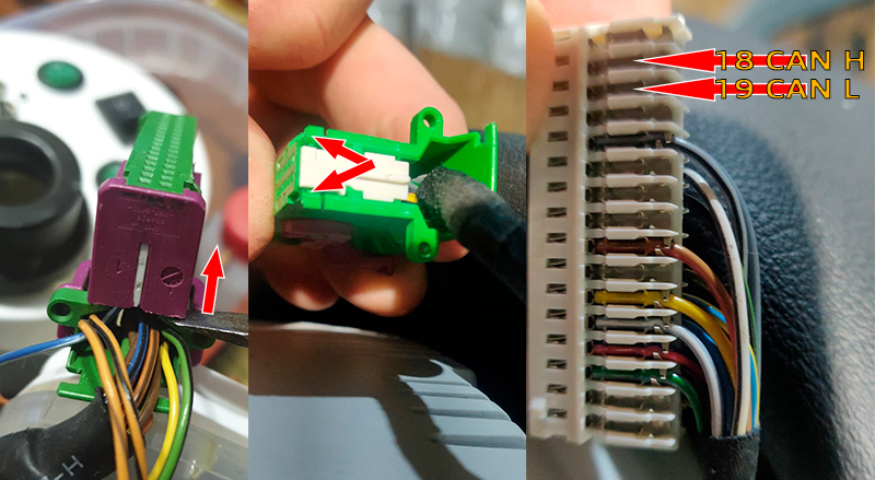
1.9. ОЧЕНЬ
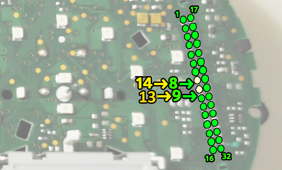
ВАЖНО: ВАРИАНТ
1 Необходимо найти и перерезать дорожки от контактов 17,18,19 серого разъема приборки. После этого убедитесь, что на контактах 17,18,19 контактов 0 вольт. Ниже вы можете увидеть фотографии некоторых кластеров. На вашем устройстве треки могут быть расположены в другом месте.
|
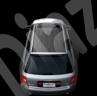
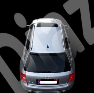
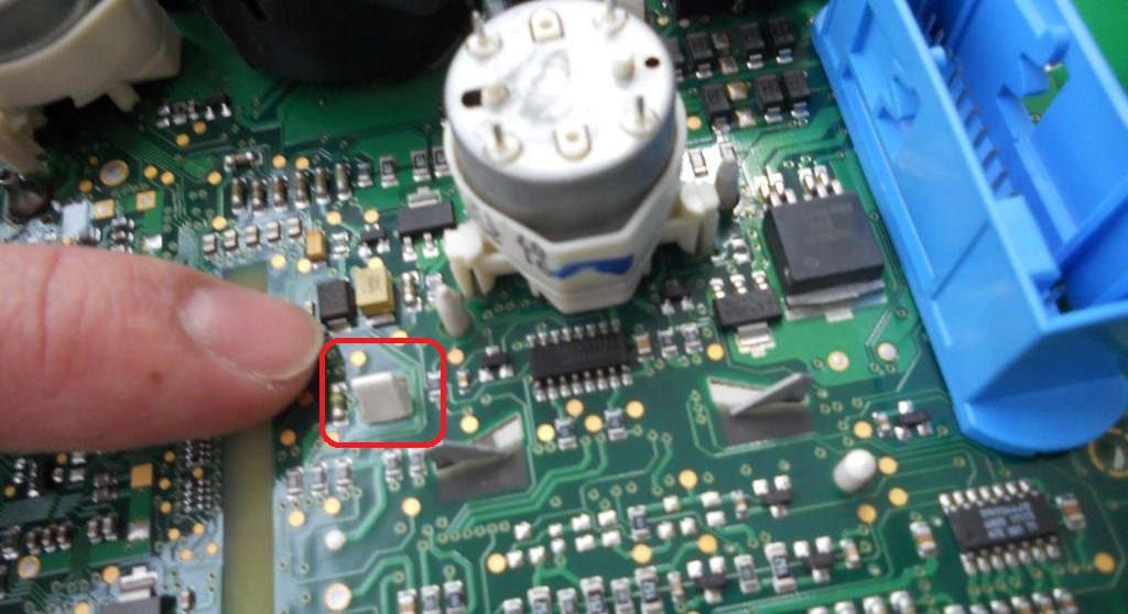
1.9. ОЧЕНЬ
ВАЖНО: ВАРИАНТ 2 Если вы не хотитерезать дорожки необходимо найти удалить резисторы питания контактов 17,18,19 серого разъема приборки. После этого убедитесь, что на контактах 17,18,19 контактов 0 вольт. Ниже вы можете увидеть фотографии некоторых кластеров. На вашем устройстве треки могут быть расположены в другом месте. |
|
||||||||||||||
|
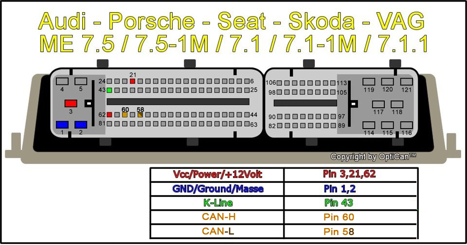
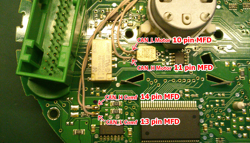
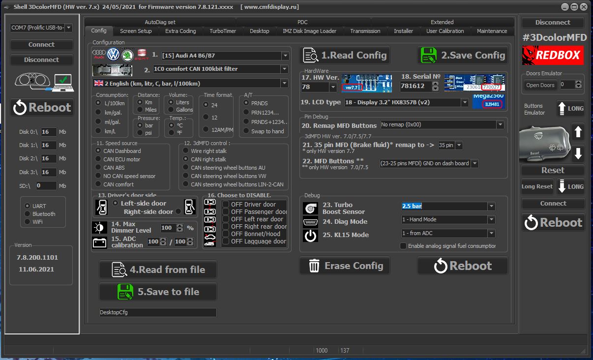
1.11. Cluster CAN-bus encoding
|
|
|
|
|
|
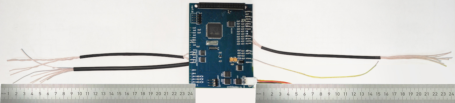
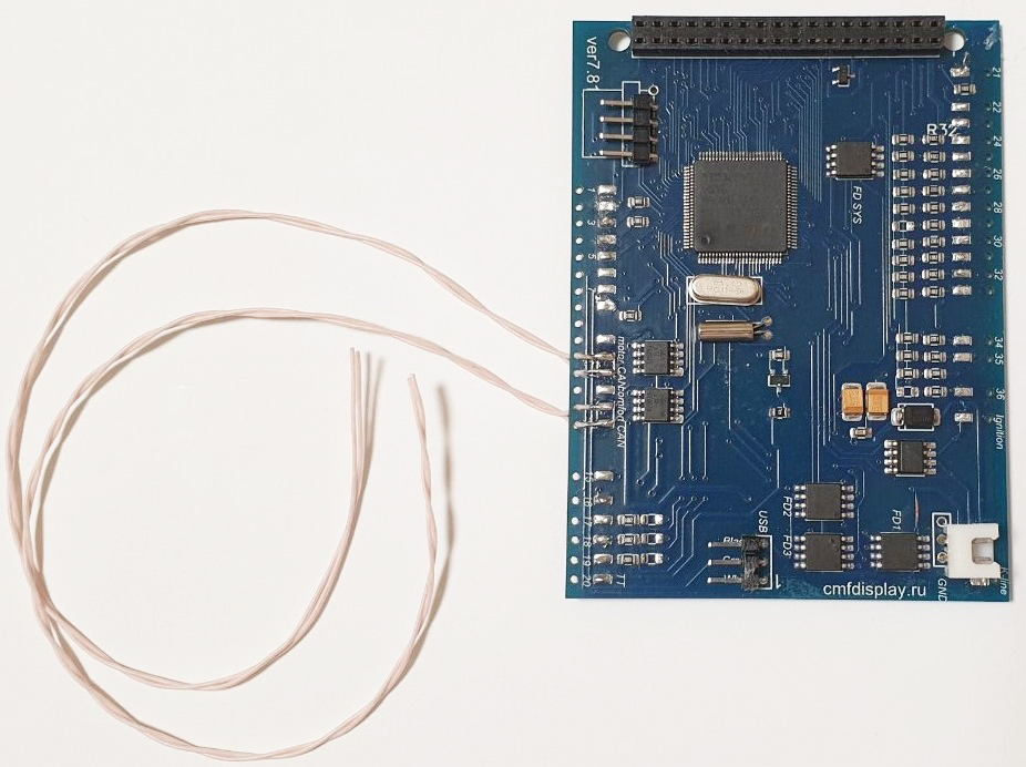
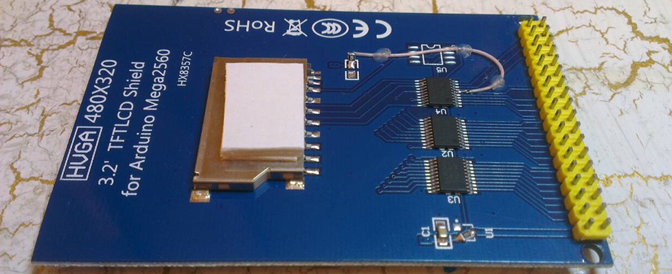
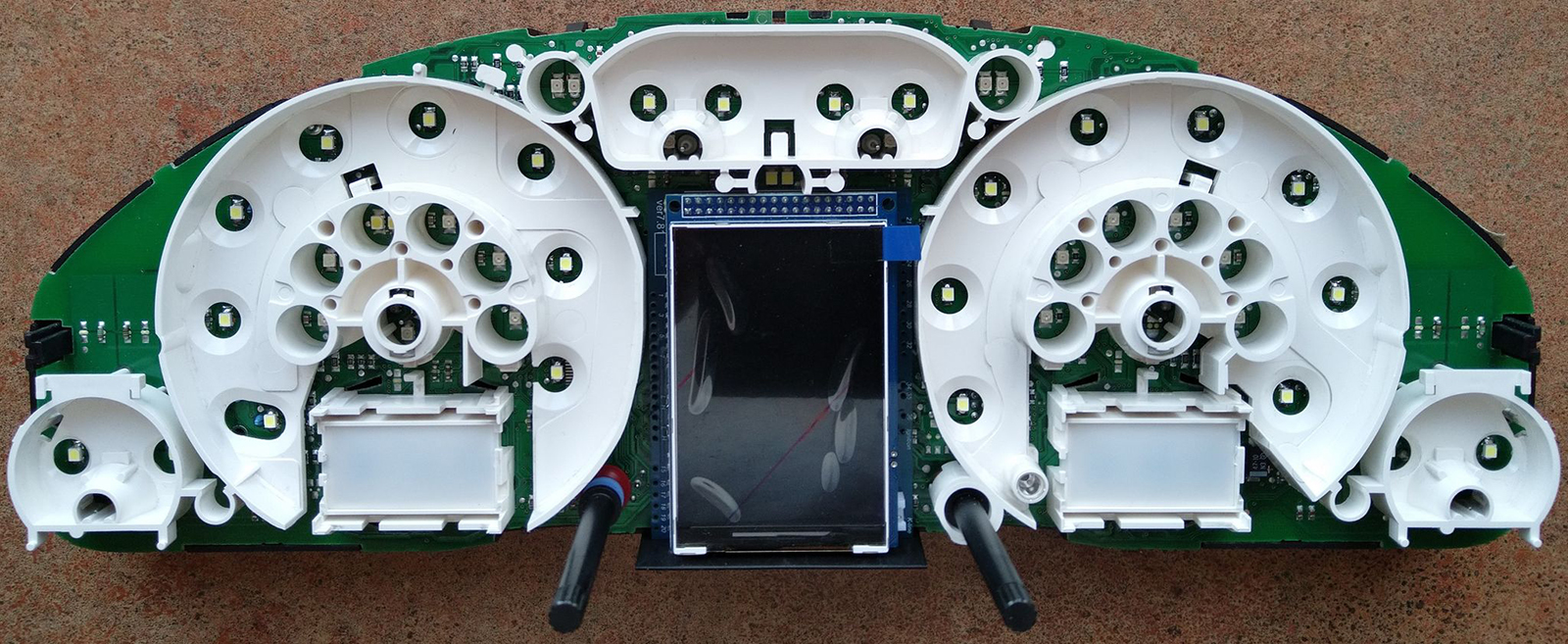
2.1. Remove LCD board from motherboard and Stretch the wires from MFD motherboard to the blue and green connectors through the holes in the cluster`s board. 2.1. Снимите ЖК-дисплей и протяните провода от материнской платы MFD к синему и зеленому разъемам через отверстия в плате кластера. |
|
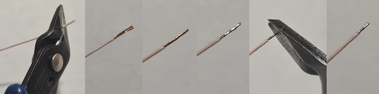
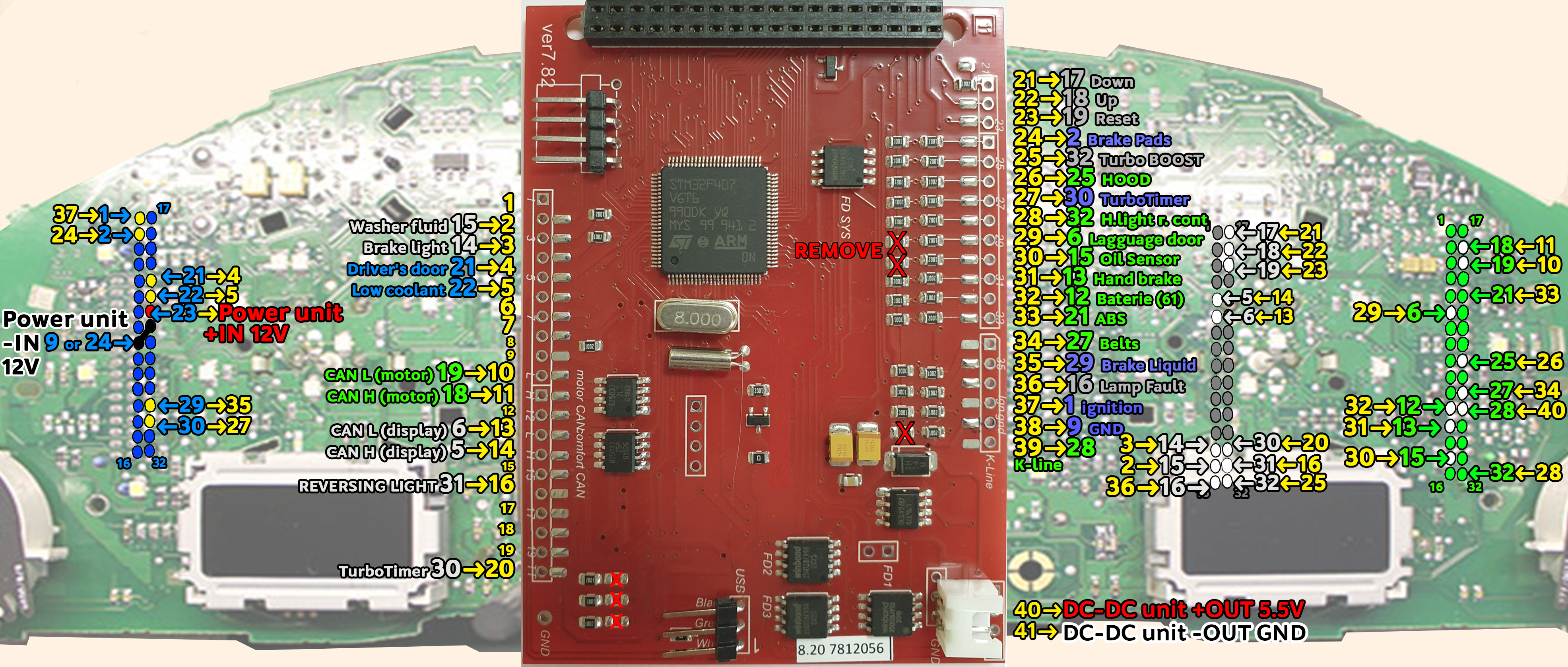
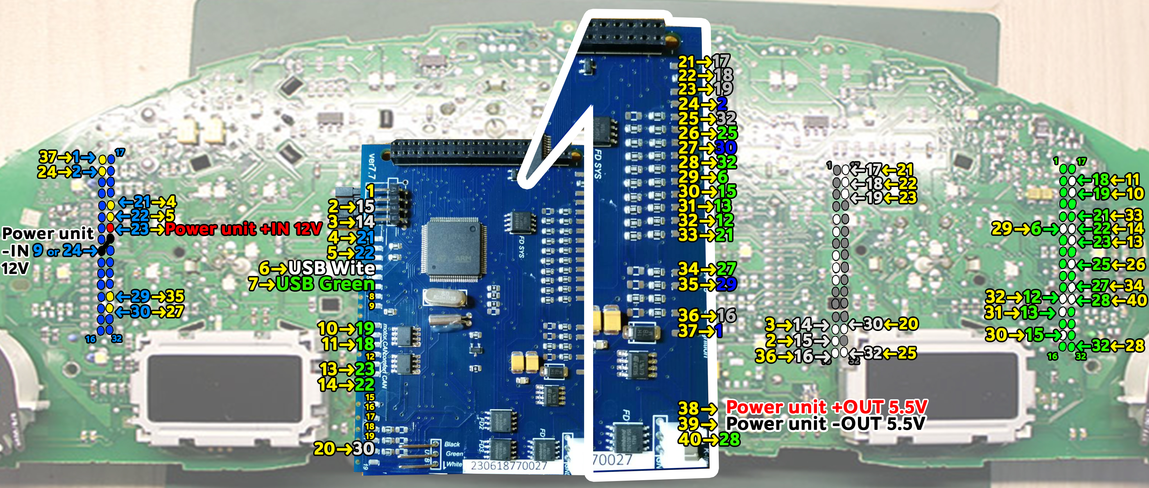
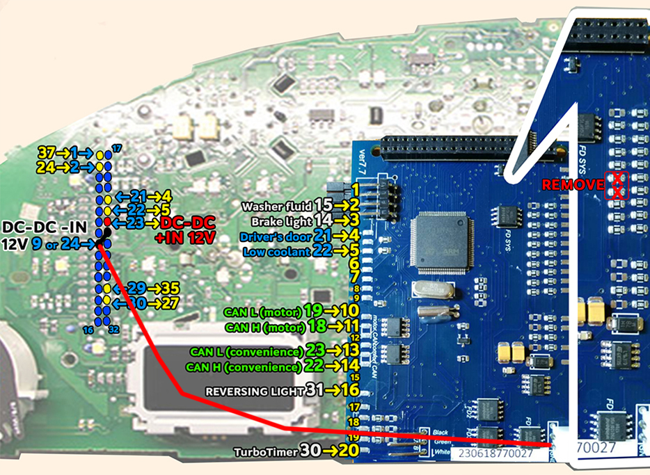
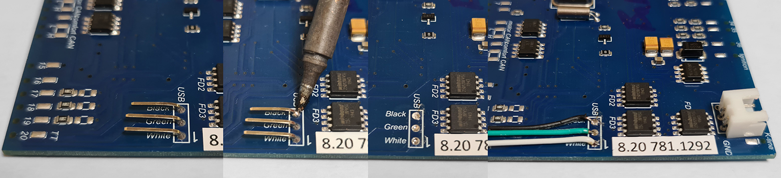
2.2 Start to soldering wires according to the table. Wires should be cleaned from Isolation, twisted and tin plated. 2.2 Приступаем к пайке проводов по таблице. Провода должны быть очищены от изоляции, скручены и залужены. |
|
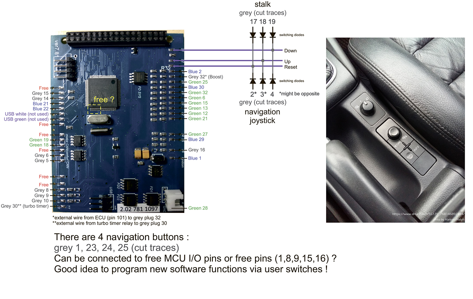
2.2.1 If you have an additional joystick to control the regular navigation system, it can also be used to control 3dMFD. 2.2.1 Если у вас установлен дополнительный джойстак управления штатной навигационной системы, его также можно задействовать для управления 3dMFD. |
|
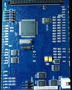
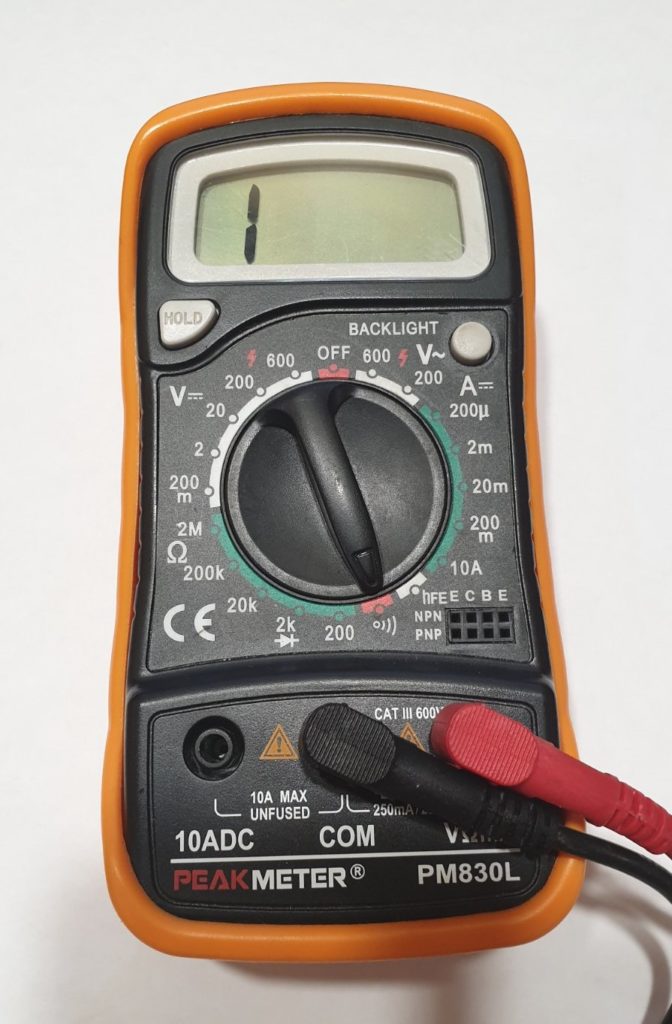
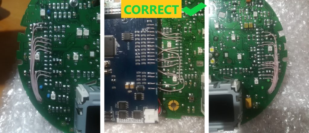
2.3
Take the multimeter, set it to Diode (Ring) mode. Using multimeter and wiring diagram, find the wires you need and solder them to the connector pins.
2.3 Используйте мультиметр,
установите его в режим диода (прозвонка)
и схему подключения, найдите нужные провода и припаивайте
их |
 |
![]()

![]()
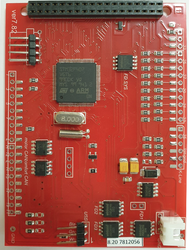 |
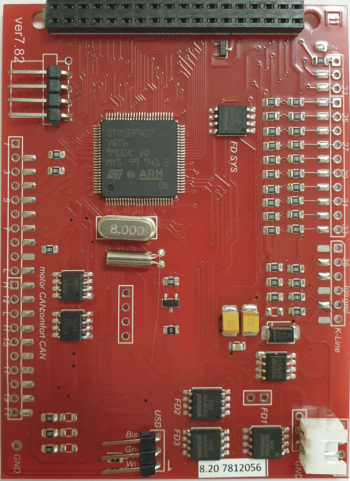
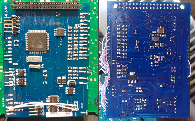
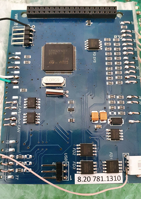
2.3.1 The
new board revision 7.8.2 has minor differences.
Новая ревизия
платы 7.8.2 имеет небольшие отличия.
|
|
2.4. Twist in a spiral
CAN-bus connection wires.
2.4 Обязательно скручивайте в спираль
провода,
|
|
|
2.5.
There are 2 ways to connect CAN bus wires. Choose what is
convenient for you. 2.5. Есть два варианта подключения проводов CAN-шины. |
|
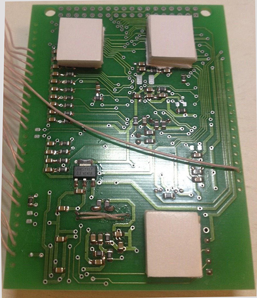
1-st way: solder the wires to to the pins of the green connector 1-й вариант подключить провода к пинал разъема |
2-nd way: solder the wires to the points, indicated in the photo 2-й вариант подключить провода к точкам на тыльной стороне платы приборки. |
||
 |
 |
|
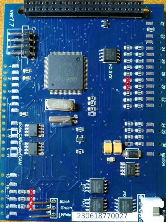
2.6. Important!Remove the resistors from the 3dMFD board as shown in the picture.
2.6. Важно! |
|
|
|

|
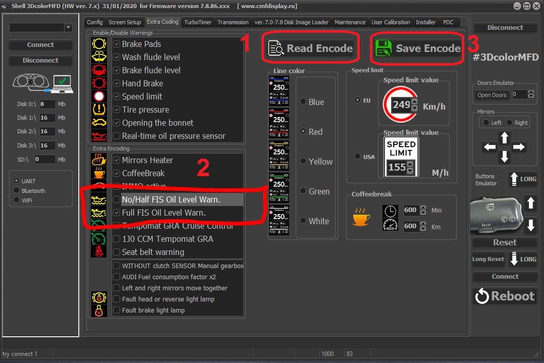
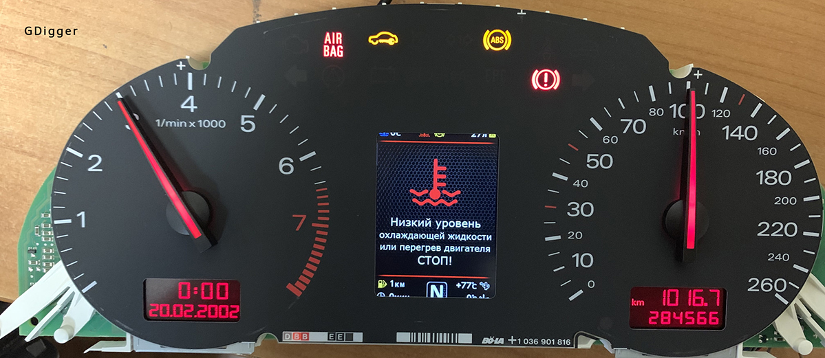
После установки необходимо подключить MFD к программе Shell и настроить предупреждение о низком уровне масла для кластера FullFIS как показанно ниже на картинке.
Shell program link:
Video instruction:
|
|
|
|
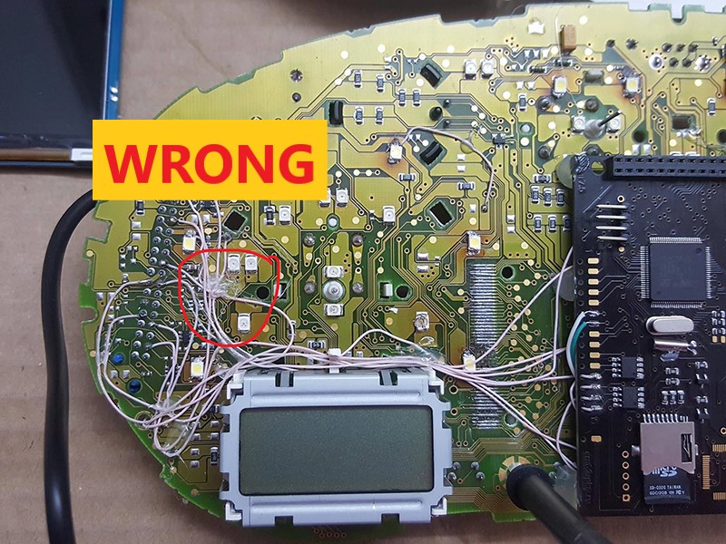
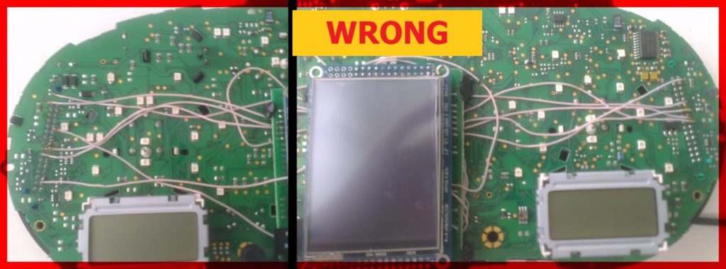
2.7. Lay the wires in such a way that they do not interfere with the installation of white Light diffuser. 2.7. Провода следует тянуть с тыльной стороны или, как показано выше,так чтобы при сборке приборки провода не мешали.
|
|
2.7. Wires should be pulled from the back side Or as shown above, so they do not interfere with the assembly of the device. So it's not right!
2.7. Провода следует тянуть с тыльной стороны или, как показано выше,так чтобы при сборке приборки провода не мешали.
|
 |
|
 |
|
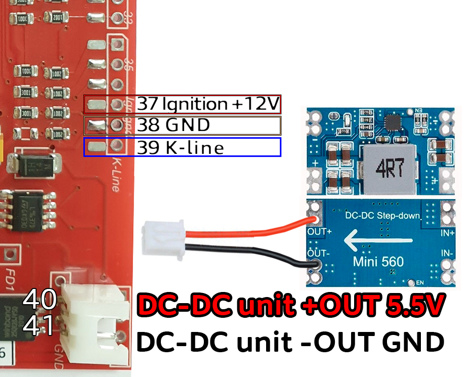
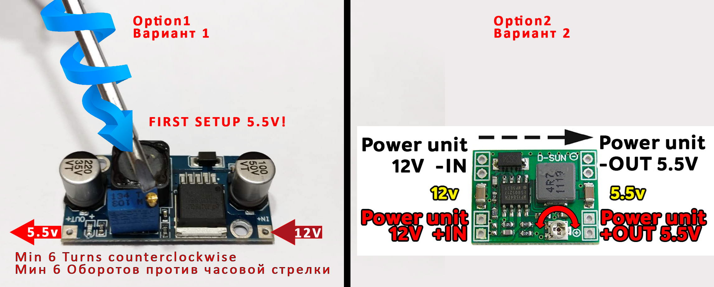
Attention! 2.8. Before installing the power supply, you need to solder the wires to it contacts + IN - IN and + OUT - OUT, then apply a current of 12V to + IN - IN, and connect the + OUT - OUT wires to the tester. Now we need to adjust the output current. Using a small flat screwdriver slowly rotate the special metal knob (figure 1 in the picture.) Clockwise Arrow, until, at us on the tester will not appear 5,5v in an output voltage. Next we place the power supply unit on the back side, we bring to its contacts the wires from the blue connector.
9
pin of blue
GND connector is
connected to the e - IN on
the power supply board.
ВНИМАНИЕ! затем подайте ток 12 В на + IN - IN и подключите провода + OUT - OUT к тестеру. Теперь нам нужно настроить выходной ток. С помощью небольшой плоской отвертки медленно поверните специальный винт (цифра 1 на рисунке) по часовой стрелке много раз, до тех пор, пока, у нас на тестере не появится +5,5v в выходном напряжении. Далее размещаем блок питания с тыльной стороны, подводим к его контактам провода от зеленого разъема. 9 контакт синего разъема - GND подключен к разъему e-IN на плате блока питания. 23 контакт синего разъема +12V подключен к + IN на плате блока питания,
|
|
2.8. Connect - OUT Connects to 39 pin MFD Choose the place of installation of the power supply so that during assembly it does not interfere. Here are the possible
2.6. Соедините
|
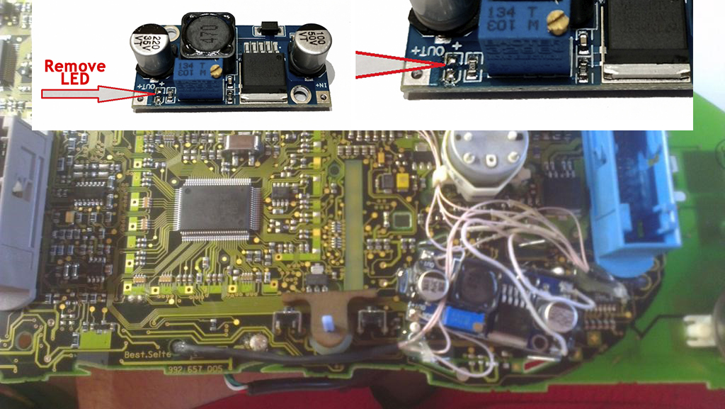
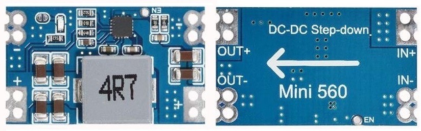
This type of DC-DC converter is already set to 5.2V
Этот тип DC-DC конвертер уже настроен на 5.2В
|
After wiring, lay it so that they do not interfere with further assembly. Need to call all contacts and check on the table to avoid confusion anywhere.
После прокладки проводов необходимо прозвонить с помошью мультиметра все контакты и проверить по таблице, чтобы нигде не было ошибки
|
|
Attention! For reliable operation of 3dMFD , it is imperative to make an additional GND connection as shown in the photo
Внимание! |
 |
 |
|
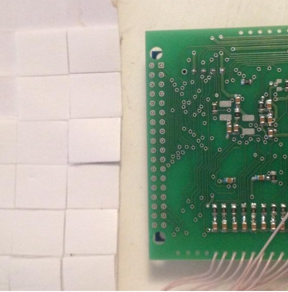
3. We take
double-sided adhesive tape on a foamy basis, cut the squares 1cm X 1cm.
3. Берем двусторонний скотч и вырезаем квадраты 1см Х 1см. |
3.1. We collect these squares in 3 floors.
3.1. Собираем скотч в 3 слоя. |
 |
 |
|
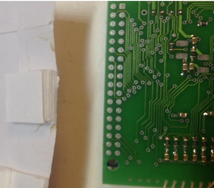
3.2.
And we place it on the
3dMFD board, the height of the adhesive tape should be enough so
that the 3dMFD board does not touch the cluster board.
3.2. И
размещаем на плате 3dMFD, высоты скотча
должно быть достаточно, чтобы плата 3dMFD
не касалась платы приборки. |
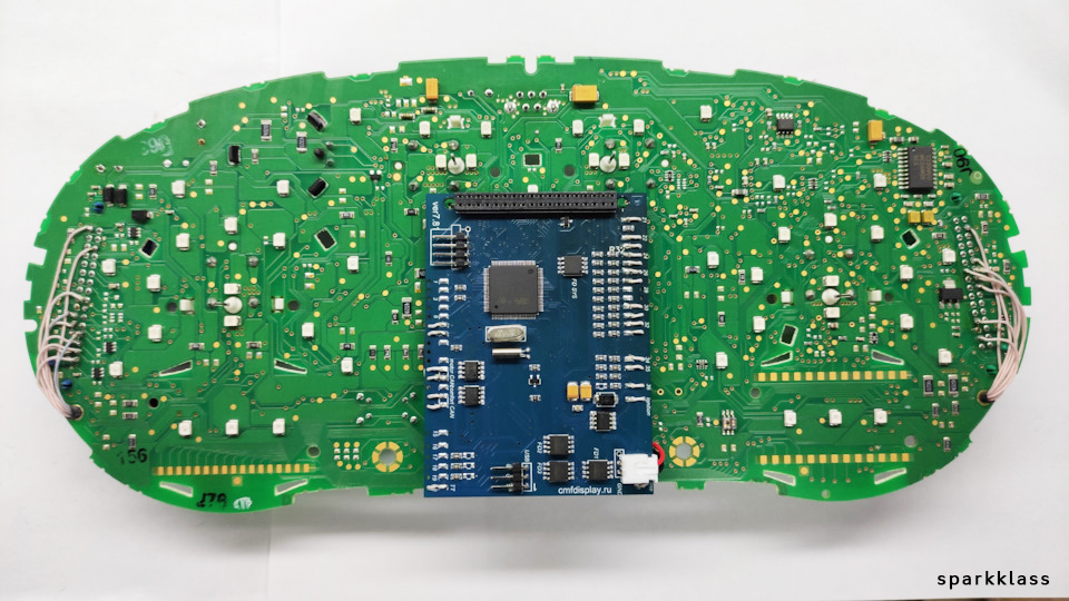
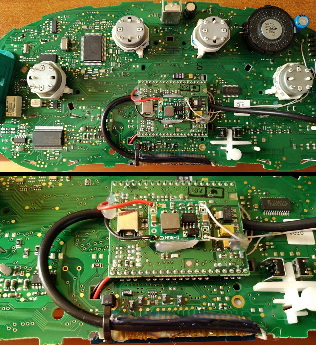
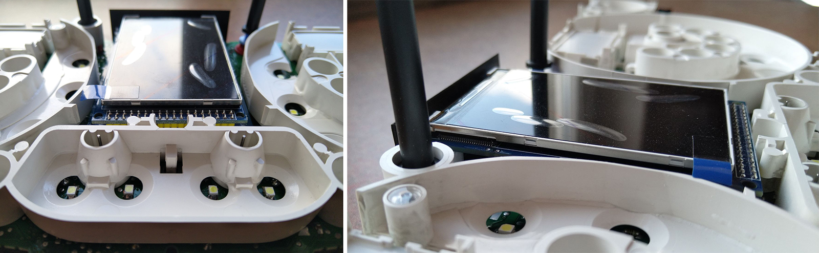
3.3. Place the module so that it is placed in the window of the device 3.3. Разместите модуль так, чтобы он находился в оконе маски приборки. |
 |
 |
|
3.4.
For greater reliability, when the module is already installed on the
board,
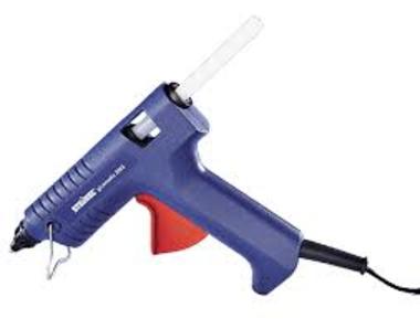
and you calibrated it in the window so that there were no distortions, it is better to fix it. Its hot glue along the edges of the module.
3.4. Для большей надежности, когда модуль уже установлен на плате, а вы откалибровали дисплей так чтобы не было перекосов, вы можете зафиксирвать палту 3dMFD горячим клем по краям модуля. не нужно заливать полностью всю плату в 2 -3 точках будет достаточно. |
|
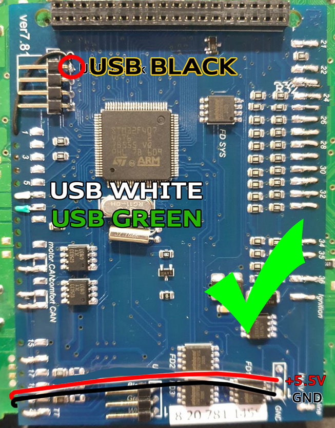
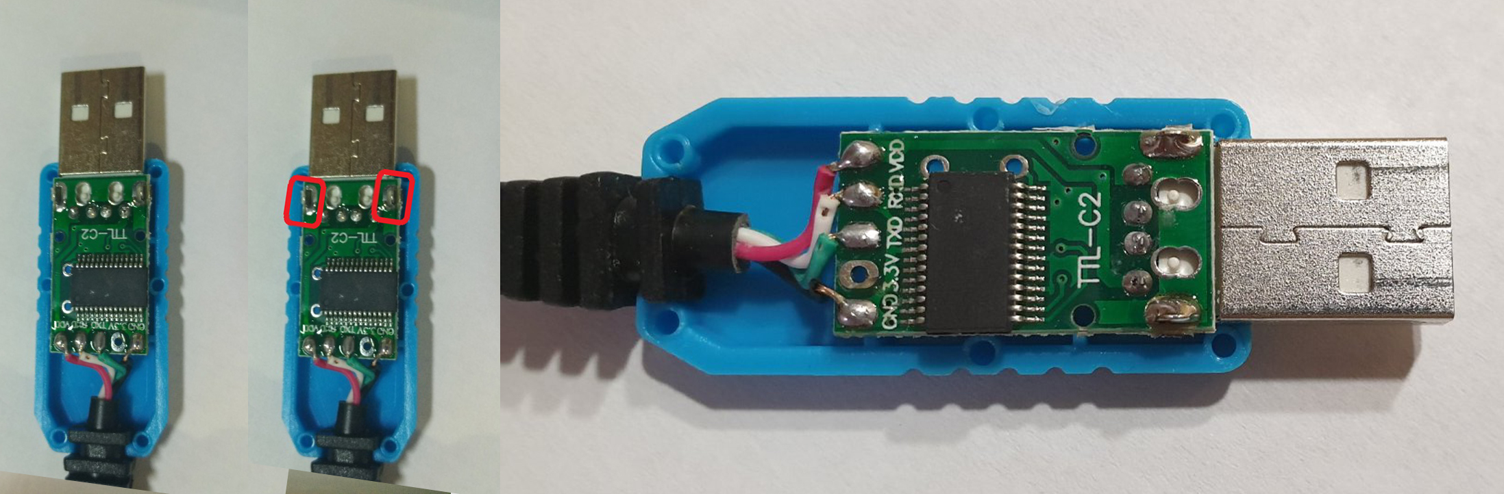
4. The USB
cable should be fixed with glue. Red USB wire do not use, cut it off.
4. Кабель
USB следует закрепить клеем. |
|
4.1.
1-WAY
of USB connection
4.1. 1-Й вариант подключения USB |
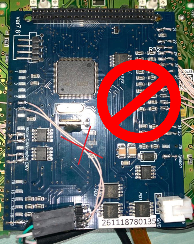
4.1.
WRONG-WAY
of USB connection
4.1. Неправильный вариант подключения USB |
 |
 |
|
4.1.
2-WAY
of USB connection
4.1. 2-Й вариант подключения USB |
|
4.2.
OpenUSB
And solder
the metal ears marked in red.
4.2. Откройте USB и припаивайте металлические уши отмеченные красным |

|
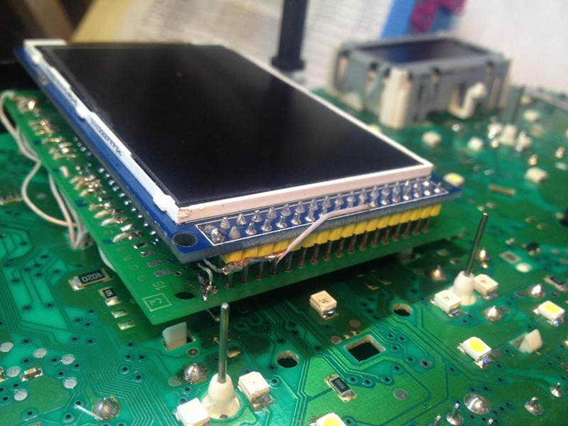
5.
Before installing the display, you need to glue double-sided
adhesive tape into three layers on the back of the display to lock
the display.
5. Перед
установкой дисплея нужно приклеить двухсторонний скотч, для того
чтобы создать дополнительную опору |
|
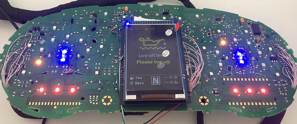
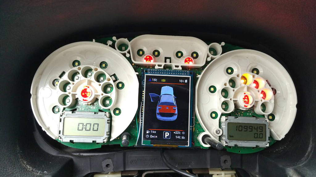
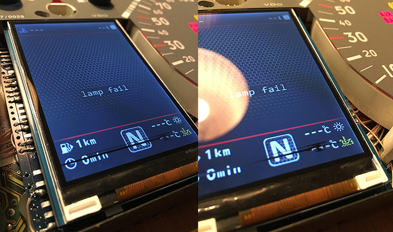
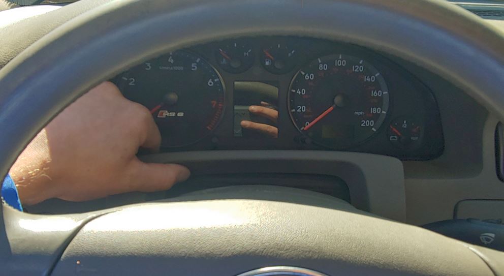
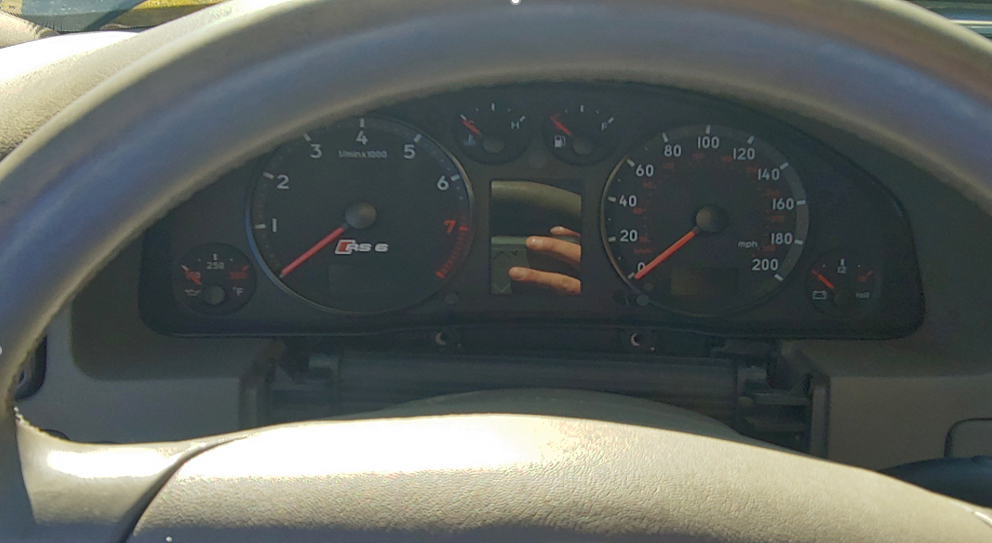
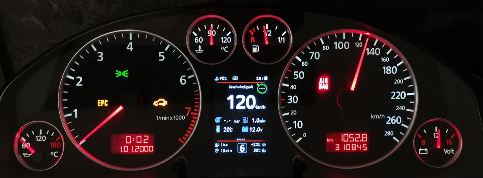
6. After you solder the wires and set the display to its place, you need to test the 3dMFD performance in the car to make sure everything is properly installed and working well.
6. После того, как вы припаяли все провода и установите дисплей на место, dам необходимо протестировать работу 3dMFD в автомобиле, чтобы убедиться, что все правильно установлено и работает нормально. |
|
7. Next, you
need to glue the matte protective film so that the display does not
glare in the sun. Unfortunately, the film may not always be included, but it is easy to find on Marketplace, you can use a polyurethane matte screen protector for any smartphone just cut out with scissors to the right size.
7. Далее нужно приклеить матовую
защитную пленку, чтобы дисплей не бликовал на солнце. |
|
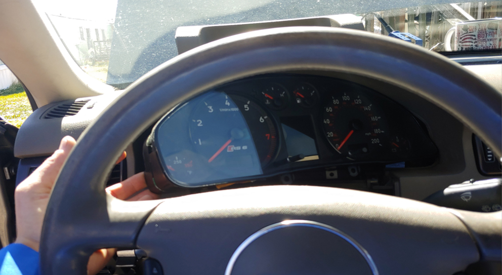
Attention!
BCarefully install the cluster case!
Внимание!
Аккуратно устанавливайте маску приборки! |
|
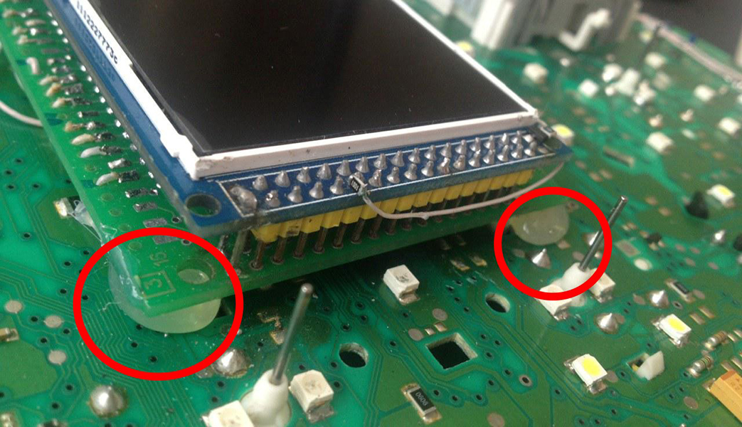
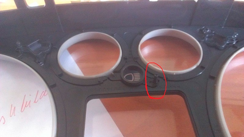
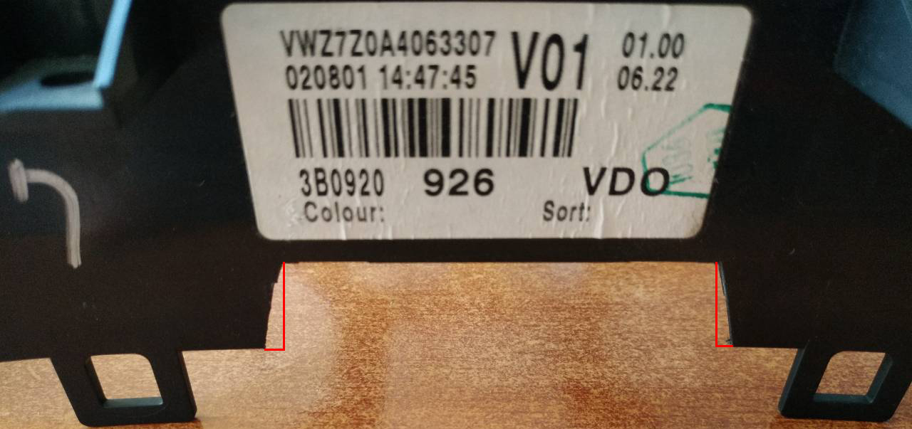
9.1. Cut off the main beam guide part. On the red line. Leave the semicircle. 9.1. Отрежьте пластик как показано на фото |
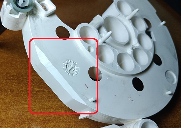
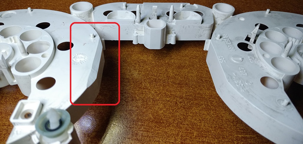
9.2. Cut off the protruding part!
9.2. Отрежьте пластиковый
штырь |
|
|
|
|
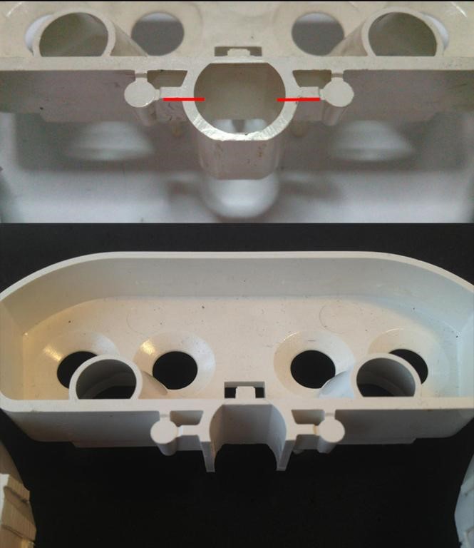
|
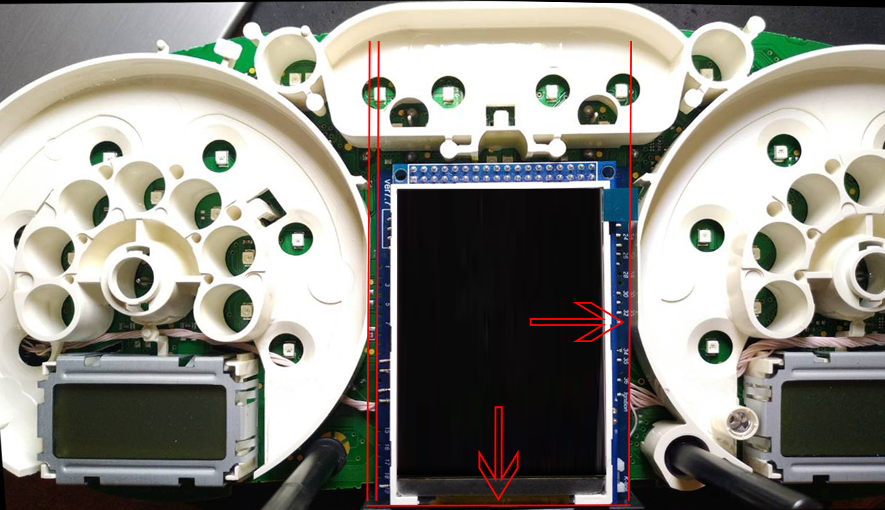
9.2. Install a white diffuser and cut off the excess (as shown in the picture), then place the display and align it so that it clearly fits into the cluster window. 9.2. Установите белый диффузор и отрежьте лишнее (как показано на картинке), затем поместите дисплей и выровняйте его так, чтобы он четко вписывался в окно приборки. |
|
9.2.1 Open the USB and solder what is marked
in red. 9 .2.1 Откройте USB и припаяйте то, что отмечено красным цветом. |
 |
|
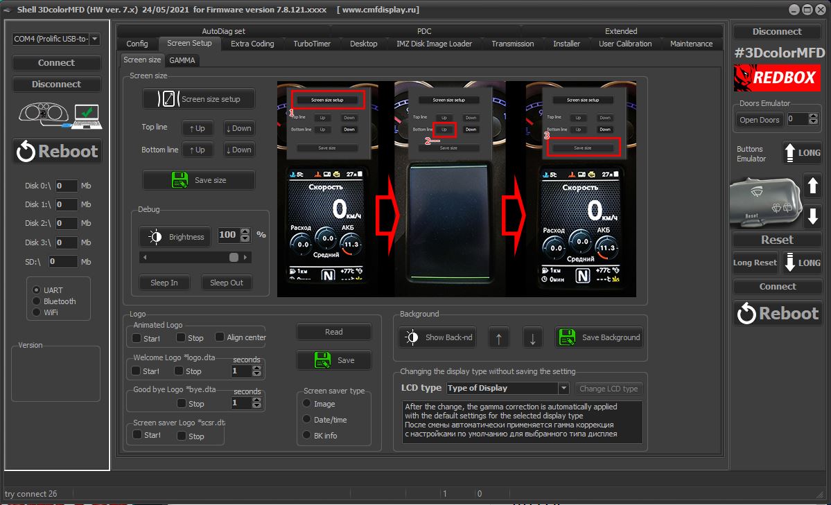
9.3.Using the Shell -> Screen Size program,
adjust the display frames according to the window in the tidy scale. 9 .3. С помощью программы Shell -> Screen Size настройте рамки дисплея по окну в шкале приборки. |
|
11. Boost pressure controlINSTALLING BOOST WIRE TO CLUSTER
11. Подключить отображение давления наддува
|
|
1)
(audi b5 push down on the plastic trim then pull outwards to
your chest) (audi c5 pull plastic trim outwards to your chest) |
|
1) (audi b5 надавите на пластиковую отделку, затем
потяните ее наружу к груди) (audi c5 потяните пластиковую отделку
наружу к груди) |
|
|
|
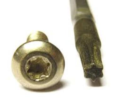
2)
(audi b5 has 2 torx 20 bit screws) (audi c5 !!!GLUED
PHILLIPS!!! MAKE SURE TO HAVE A TIGHT FITTING PHILLIPS WITH HEAVY
PRESSURE) |
|
|
2) (audi b5 имеет 2 винта torx 20 bit) (audi c5
!!!GLUED PHILLIPS!!! УБЕДИТЕСЬ, ЧТО У ВАС ЕСТЬ ПЛОТНО ПРИЛЕГАЮЩИЙ
КРЕСТОВОЙ ВИНТ С СИЛЬНЫМ ДАВЛЕНИЕМ) |
|
|
|
|
3)
grap speedometer button thingys and wiggle it out (some c5s
can be a pain take your time) |
|
|
3) зажмите кнопку спидометра и выкрутите ее (на
некоторых c5 это может быть сложно, не торопитесь). |
|
|
|
|
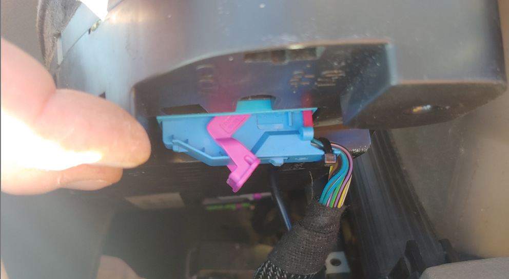
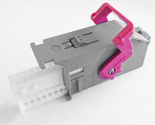
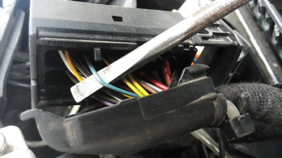
4)
there it a tab that lock the flip up locking tab that will
need to be pushed in as you flip up the purple flip tab. Do this for
all 3 connectors. |
|
|
4) там есть язычок, который фиксирует откидной
стопорный язычок, который нужно будет задвинуть, когда вы будете
откидывать вверх фиолетовый откидной язычок. Сделайте это для всех 3
разъемов. |
|
|
|
|
5)
slide out the cluster flipping the bottom up and around your
dash |
|
|
5) выдвиньте кластер, перевернув его нижней частью
вверх и вокруг вашей приборной панели |
|
|
|
|
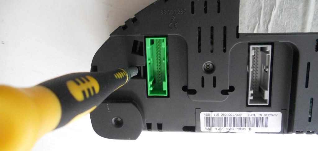
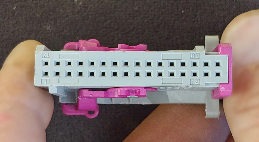
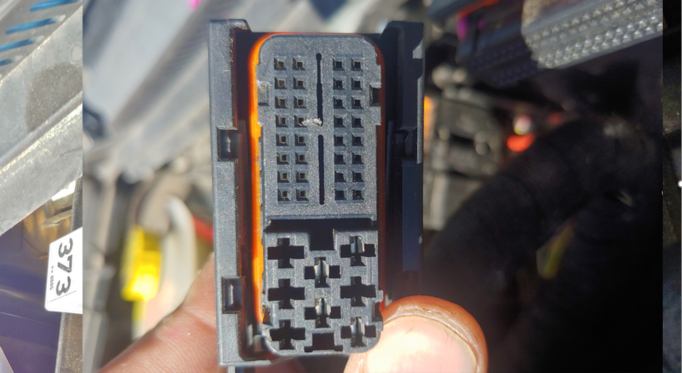
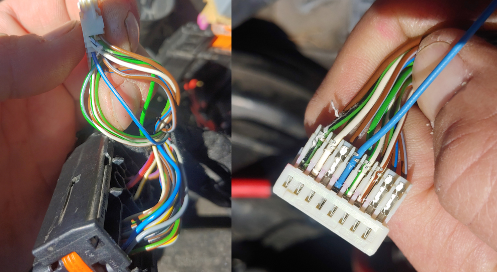
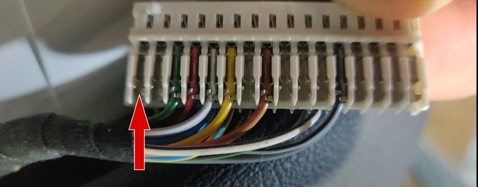
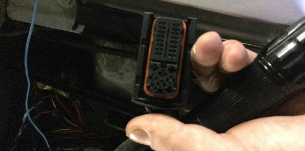
INSTALLING THE WIRE 1) After removing the cluster you see 3 connectors Blue, Grey and Green for this stepp we will need the Grey connector with the plug facing us. To the far left top is pin 1 far right bottom is pin 32
(bottom is the purple slide) |
|
|
УСТАНОВКА ПРОВОДА |
|
|
|
|
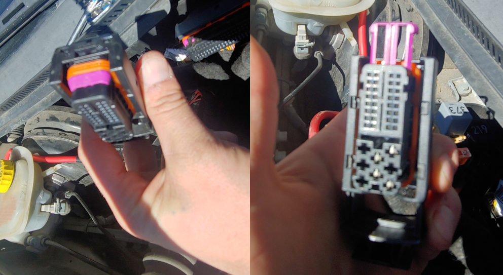
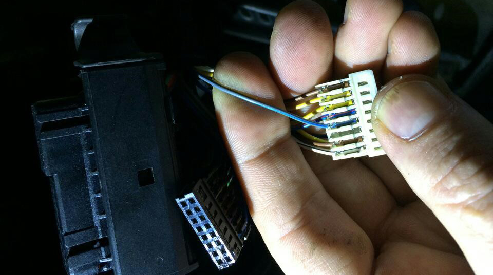
2) pull the purple tab straight off the connector pulling the inner
white plasic out from the shell. Make sure to know the direction the
inner white plasic faces as you could put it in backwards but common
sense tells you what way to slide as your wires run out of the
shell. With the white inner plastic facing you in the right
orientation locate pin 32 (right far bottom) pushing in the new pin. |
|
|
2) потяните за фиолетовый язычок прямо от разъема, вытаскивая внутреннюю белую пластину из корпуса. Убедитесь, что вы знаете, в каком направлении обращена внутренняя белая пластмасса, так как вы можете вставить ее в обратном направлении, но здравый смысл подскажет вам, в какую сторону скользить, так как ваши провода выходят из корпуса. С белым внутренним пластиком, обращенным к вам в правильной ориентации, найдите контакт 32 (крайний правый снизу), вставляя новый контакт. |
|
|
|
|
Make sure to solder and heat shrink as its the proper sure way
knowing you will not have to redo your work! |
|
|
Убедитесь в том, что пайка и термоусадка - это
надежный способ, который поможет вам избежать повторного ремонта! |
|
|
|
|
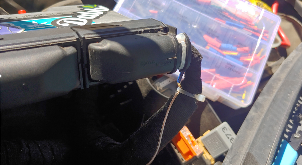
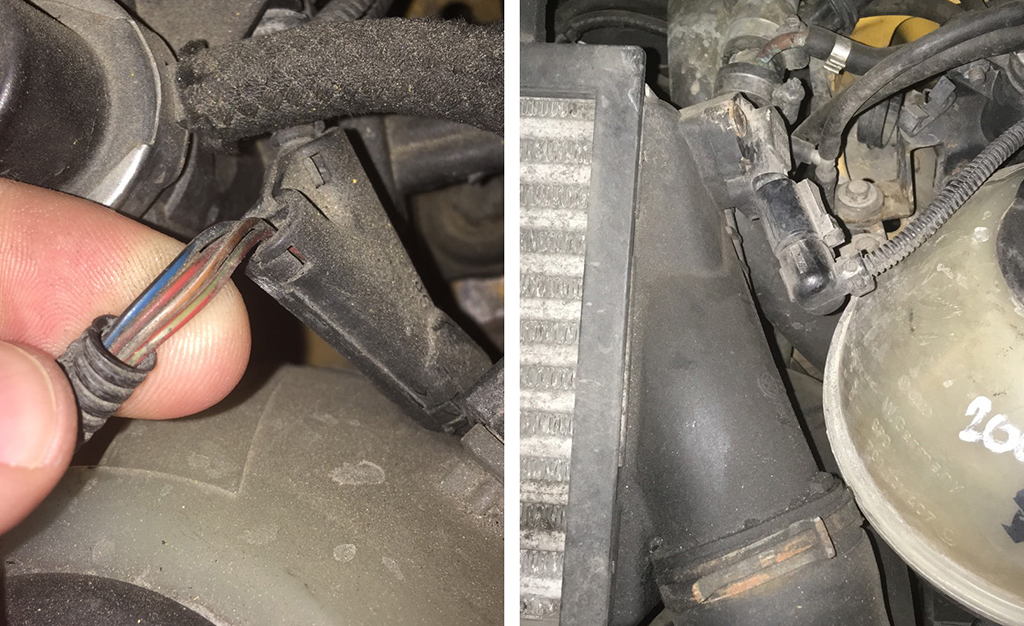
3) running
you boost wire through the dash up through the ecu where the factory
wires are ran is the best choice as your able to ziptie them
together knowing that they are secure! |
|
|
3) прокладка провода наддува через приборную
панель до ЭБУ, где проходят заводские провода, является лучшим
выбором, так как вы можете застегнуть их вместе, зная, что они
надежны! |
|
|
|
|
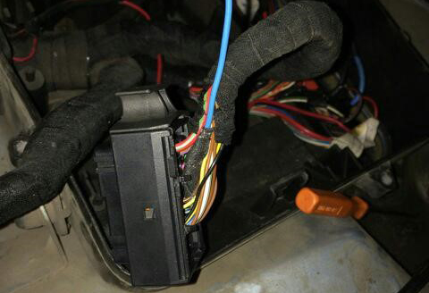
4) removing the ecu is quite simple as there is 5 8mm bolts holding
on the weather cover. Use a flat head screwdriver pushing down and
out releasing the clip. You will need to cut the outter security
shell that clams it together. ( cut a line across the metal that
covers the one clip and pull it apart separating the ecu from the
shell making the plugs accessible . Be careful to not cut any wires
or yourself! |
|
|
4) Снять блок управления довольно просто,
поскольку 5 8-миллиметровых болтов удерживают погодную крышку.
Используйте плоскую отвертку, нажимая вниз и наружу, освобождая
зажим. Вам нужно будет разрезать внешнюю защитную оболочку, которая
сжимает ее вместе. ( прорежьте линию по металлу, который закрывает
один зажим, и потяните его в сторону, отделяя блок управления от
оболочки, открывая доступ к разъемам. Будьте осторожны, чтобы не
порезать провода или себя! |
|
|
|
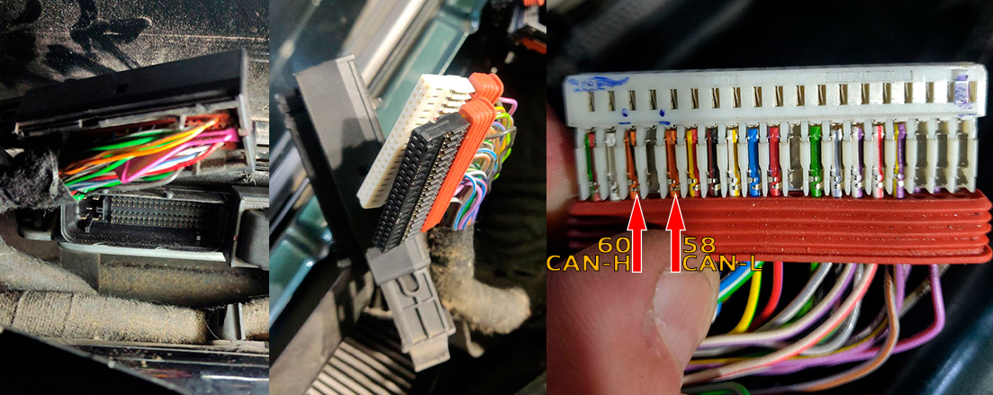
|
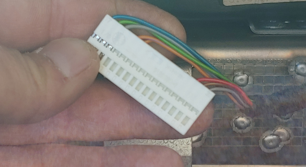
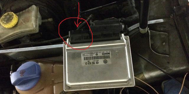
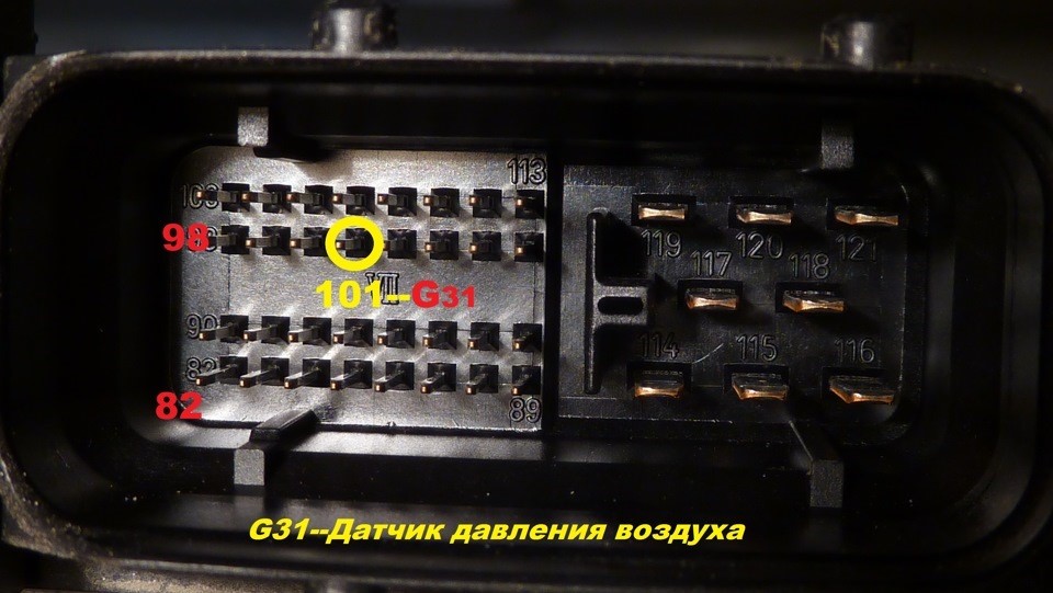
5)
Once you have the ecu out and unplugged (depending on model
PLEASE CHECK DIAGRAM BELOW) you will find pin 101 of the ECU (Audi
2.7tt) small connector. FOR ME YOU CAN SEE WHERE I MARKED IT 4TH
FROM RIGHT 2ND ROW IS MY PIN 101 FOR AUDI 2.7 |
|
|
5) После того, как вы вытащили и отсоединили блок
управления (в зависимости от модели, ПОСМОТРИТЕ ДИАГРАММУ НИЖЕ), вы
найдете контакт 101 маленького разъема ECU (Audi 2.7tt). У МЕНЯ ВЫ
МОЖЕТЕ ВИДЕТЬ, ГДЕ Я ОТМЕТИЛ ЕГО 4-Й СПРАВА 2-Й РЯД - ЭТО МОЙ
КОНТАКТ 101 ДЛЯ AUDI 2.7 |
|
|
|
|
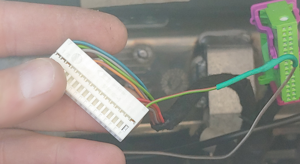
6)
Removing the inner plastic is done by unclipping to top part
of the shell and pulling the purple clip straight out this releasing
the inner plastics. This is very important to make sure what way
these go back together please take a picture so you know the correct
orientation that is goes! |
|
|
6) Снятие внутреннего пластика осуществляется
путем отсоединения верхней части корпуса и вытягивания фиолетового
зажима прямо наружу, освобождая внутренний пластик. Это очень важно
для того, чтобы убедиться, что они идут обратно вместе, пожалуйста,
сделайте фотографию, чтобы вы знали правильную ориентацию, которая
идет! |
|
|
|
|
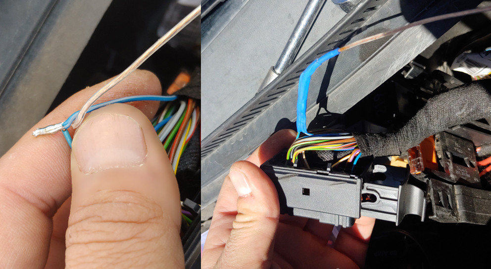
After finding pin 101 on the small connector mine turns out to be a
blue and white wire. At this point you can use a t-clamp personally
I do not like to do this as it cuts your wire leaving a few strands
for connection that can easily break or short out. Imo it is a
better job by cutting the wires and soldering them together and
shrink wrapping it for a solid connection! |
|
|
После нахождения контакта 101 на маленьком разъеме
мой провод оказался сине-белым. На этом этапе вы можете использовать
t-образный зажим, лично я не люблю этого делать, так как он
разрезает провод, оставляя несколько нитей для соединения, которые
могут легко сломаться или замкнуться. Лучше всего разрезать провода,
спаять их вместе и обмотать термоусадочной пленкой для надежного
соединения! |
|
|
|
|
Finish by
putting everything back together and ziptieing what needs to be so
there will be no loose wires possibly causing it to break
connection. |
|
|
В завершение соберите все обратно и закрепите все
необходимое, чтобы не было свободных проводов, которые могут
привести к разрыву соединения. |
|
|
|
|
When reinstalling your cluster! |
|
|
При повторной установке приборки! |
|
|
|
| Boost Wire Install Final Joshua Rios Cluster Modz Gauge |
|
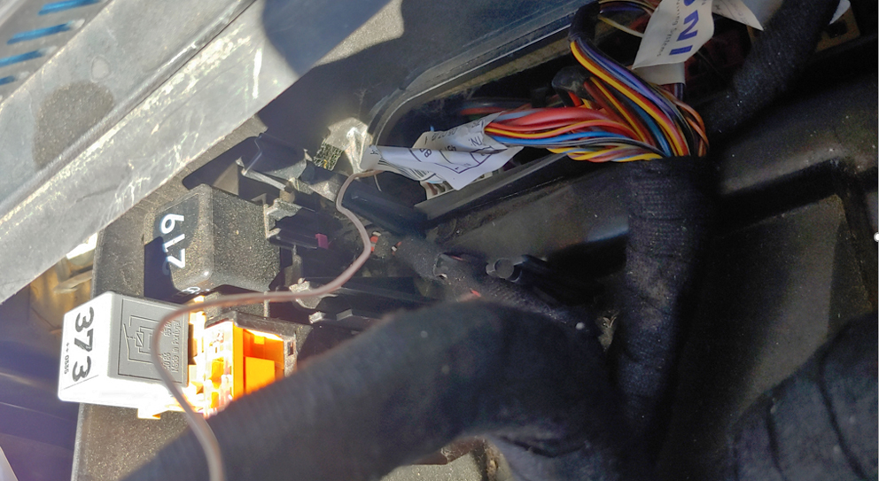
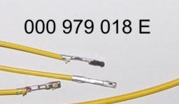
11.1. T o connect the boost pressure control, you will need to add one PIN to the dashboard 32 pin grey connector. The photo below is for example.
11.1. Чтобы подключить отображение давления наддува, вам нужно добавить провод от ЭБУд к 32 пин серого разъема. приборки. Фото ниже приведено для примера. |
 |
|
11.2.
And the other end of the wire needs
to connect the signal wire of the boost sensor to the engine ECU.
11.2. А второй
конец провода нужно подключить сигнальный
провод датчика наддува в ЭБУдвигателя.
|
|
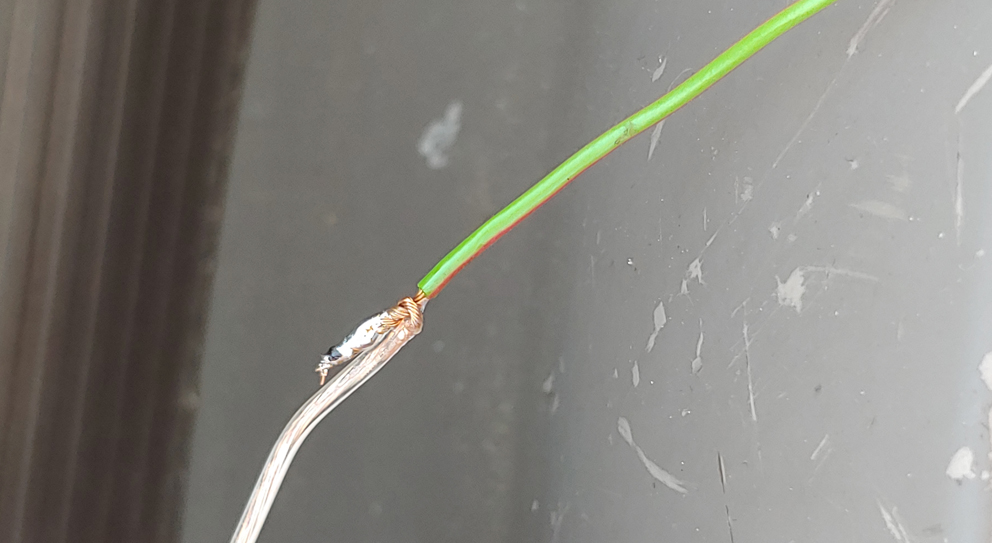
11.3. Usually it is blue - gray wire (blue with a gray bar) to the incoming on the 101st contact of a smaller brain connector. (for a gasoline engine)
On
diesel engines (AVB and others):
On
petrol (AWM and others): In general, as far as I understand, at all B5-x diesel 1.9T supercharging is connected to the 71st and the gasoline 1.8T is connected to the 101st contact. The color of the wire can vary depending on the year / engine.
8.3. Чаще всего со стороны ЭБУД к сине-серому проводу (синий с серой полосой) приходящемуна 101-й контакт меньшего разъема мозга. На дизелях (AVB и других): — 71-й контакт моторного мозга, зелено-красный провод (зеленый с красной полосой). На бензиновых (AWM и других): — 101-й контакт моторного мозга, серо-синий провод (серый с синей полосой). Отличаться может цвет провода в зависимости от года/двигателя.
|
|
 |
 |
 |
|
 |
 |
 |
|
11. После того как вы проложили сигнальный провод от ECU двигателя к приборке сделайте настройку в программе Shell, для того чтобы 3dMFD отображал давление наддува турбины. Вы должны установить тип вашего датчика давления, вы можете сделать это опытным путем подбирая его по списку в Шелл программе. |
|
12. Assembly. And then we collect everything in the reverse order without forgetting to calibrate the needles with the help of the WAG-com.
12. СБОРКА. Собирайте все в обратном порядке, не забывая калибровать иглы с помощью программы VAG-com.
|
|||
|
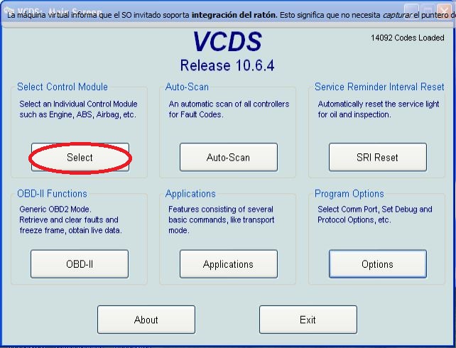
12.1. To do this, connect the device to the machine without installing the glass, connect the VAG-com.12.1 Для этого установите приборку в автомобиль (без стекла) и подключите его VAG-com. |
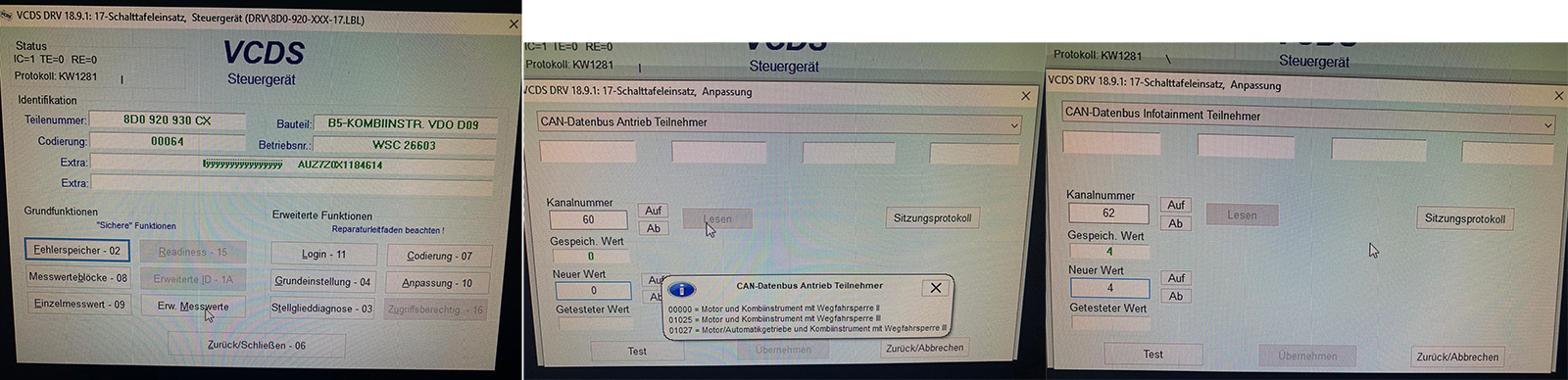
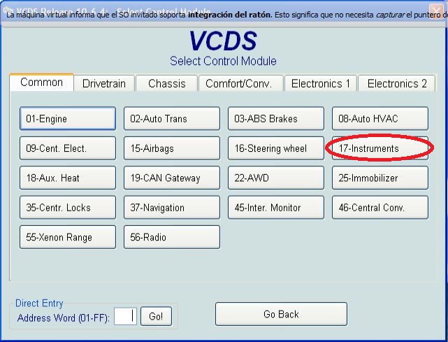
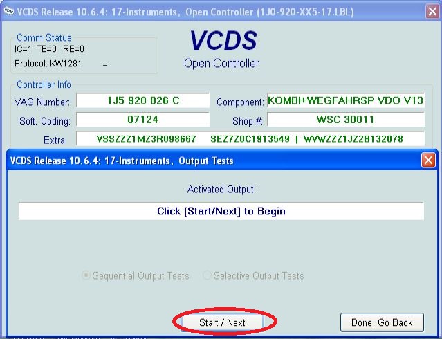
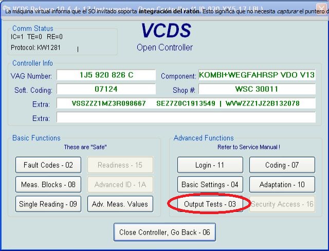
12.2. Go
into the 17-unit dash panel 12.2 Зайти в 17-блок панель приборов |
||
|
|
 |
|
12.3. Select test performers. 12.3. Выбрать "Тест исполнителей".
|
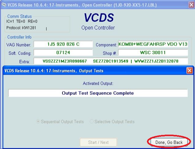
12.4. Choosing in turn a tachometer, temperature and the rest, the arrows in turn will be Do a turn on the whole scale, and then freeze on:
12.4 Сделайте тест стрелок.
|
|
|
 |
|
|
|
|
|
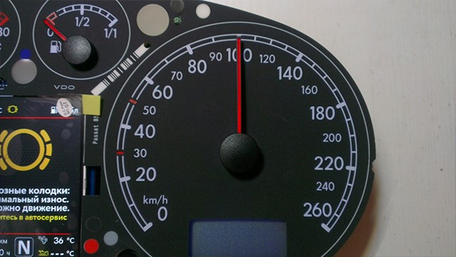
12.5. Tachometer - 3 thousand revolutions 12.5. Тахометр - на 3 тыс. оборотов |
12.6. Pace. Coolant - middle 12.6. Спидометр - на 100 км/ч |
|
|
 |
|
12.7. Fuel level - middle 12.7. Уровень температуры ОЖ - по средине |
12.8. Speedometer - at 100 km / h 12.8. Уровень топлива - по средине |
|
|
 |
|
DashBoy |
|
Then check everything
again
|
|
Затем проверьте все снова Вы не можете поворачивать стрелки слишком быстро, исправляя положение, вы можете повредить двигатели стрелки, а так же нельзя поворачивать стрелки при включенной приборке.
|
|
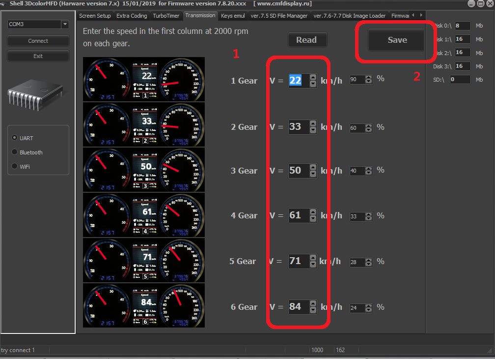
In cars with manual gearbox,
the ECU has no information about which gear you have selected, and
3dMFD cannot read it, |
|
В автомобилях с механической коробкой передач ЭБУ
двигателя не имеет информации о том, какую передачу вы
выбрали, и 3dMFD не может ее прочитать, поэтому 3dMFD показывает выбранную передачу по соотношению скорости движения и оборотов двигателя в минуту. Для калибровки необходимо ввести в первую колонку скорость движения на каждой передаче при 2000 об/мин. Кроме того, 3dmfd не означает, что включена нейтральная передача. Только при нажатии на педаль сцепления появляется сигнал N. |
|
|
|
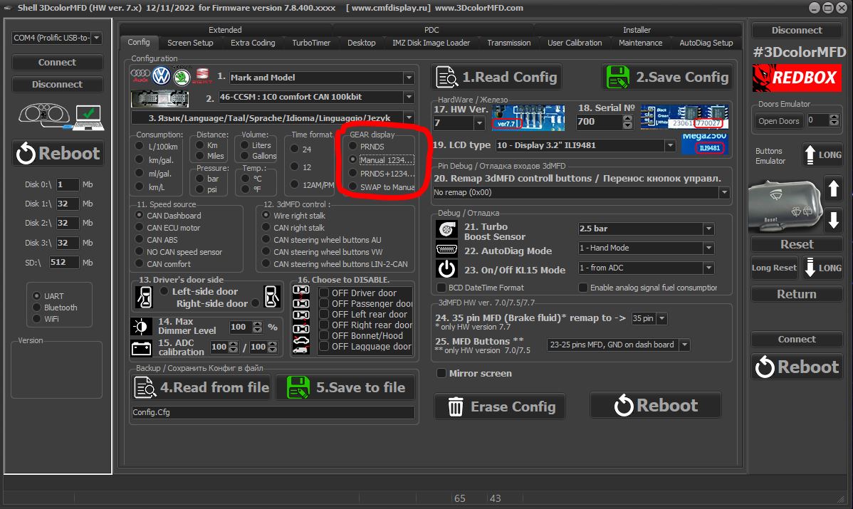
If the N signal does not appear when the clutch pedal is depressed. Check the settings in the Config tab
|
|
Если при нажатии на педаль сцепления не появляется сигнал N. проверте настройки во вкладке Конфиг |
|
|
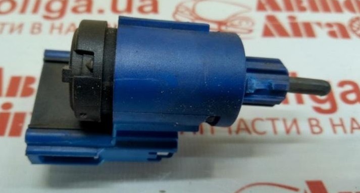
If the settings in the Configure tab are correct, but the N signal
does not appear when the clutch pedal is depressed. Check if the clutch pedal micro switch is present and working.
|
|
Если настройкf во вкладке Конфиг правильная, но при нажатии на
педаль сцепления не появляется сигнал N. Проверте наличие и работоспособность микровыключателся педали сцепления.
|
|
|
.jpg)