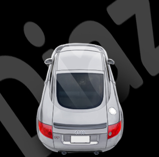
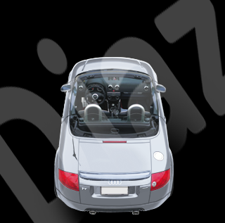
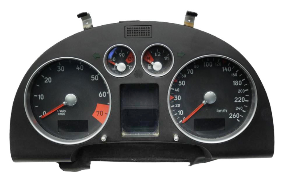
Unfortunately, the AUDI TT has a number of installation
problems.
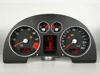
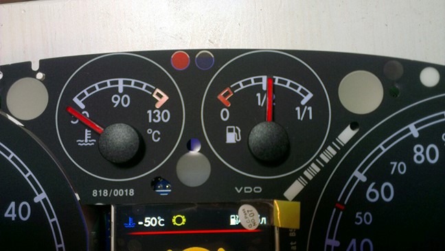
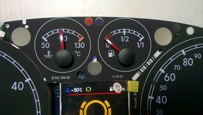
The dashboards in this car are not VDO, but JAEGER or
MAGNETTI MARELLI.
- These clusters are very difficult to install (they are
difficult to disassemble and reassemble).
- The cluster may not support can-bus operation.
- Often the AUDI TT does not have a CAN BUS engine wire from
the ECU to the cluster (especially on US market models).
- You need to set your cluster to CAN BUS.
Before ordering, you must make sure your vehicle is
compatible with 3dMFD.
You will need to do the following steps to do this:
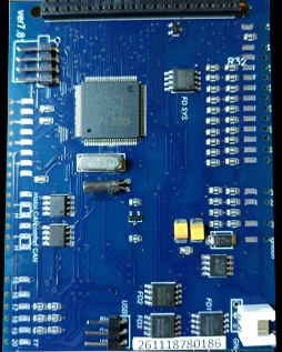
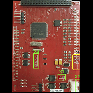
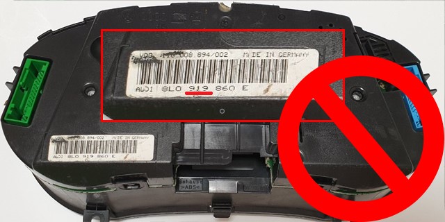
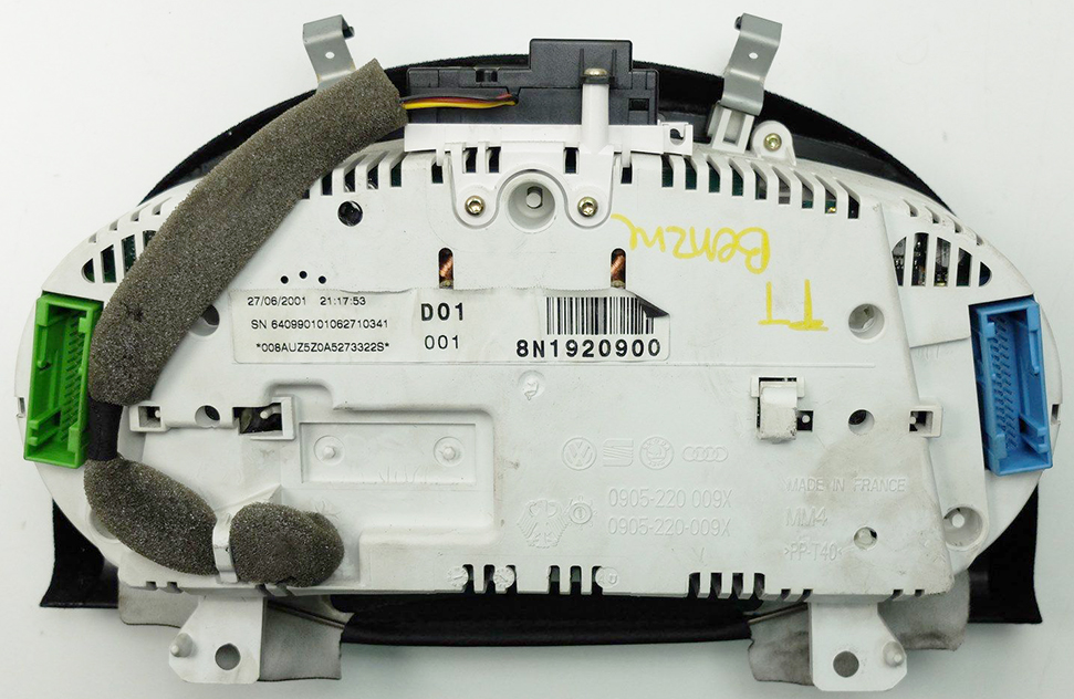
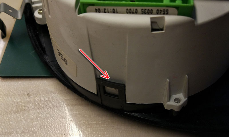
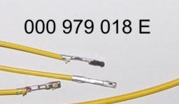
0. Check the part number
К сожалению, AUDI TT имеет ряд проблем
при установке.
В этой машине стоят приборные панели не VDO, а JAEGER или
MAGNETTI MARELLI.
- Эти приборки очень сложны для установки (их трудно
разбирать и собирать).
- Приборка может не поддерживать работу по can-bus.
- Часто AUDI TT не имеют CAN BUS проводов мотора от ECU к
кластеру (особенно в моделях для рынка в США).
- Нужно перевести работу кластера на работу по CAN BUS.
Перед заказом вы должны убедится в, что ваш автомобиль
совместим с 3dMFD.
Для этого вы должны сделать:
0. Проверить номер детали
http://www.tachopix.de/
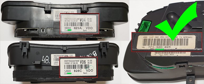
Clusters with
part number xxx920xxx are compatible with 3dMFD only.
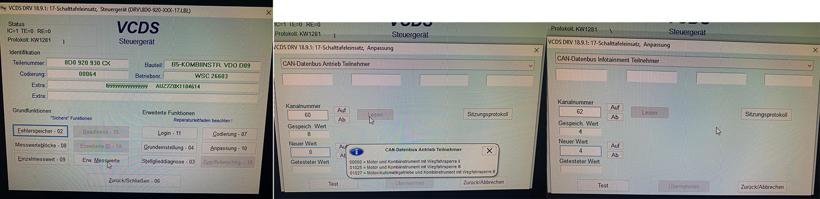
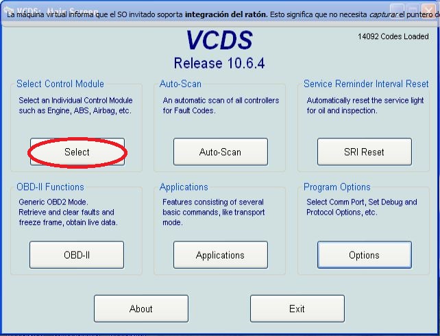
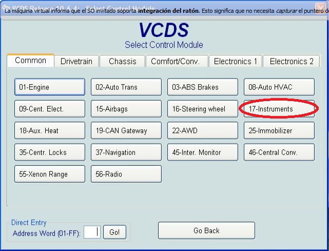
You can find out the cluster part number using VCDS:
17-
instrument panel.
xxx
920xxx
- cluster have
CAN-bus
xxx 919 xxx
-
cluster have not
CAN-bus
С 3dMFD совместимы кластеры с номером детали xxx920xxx.
Вы можете узнать номер детали кластера, используя VCDS: 17-
панель приборов.
xxx 920xxx - приборка имеет CAN-шину
xxx 919 xxx -
приборка
не имеет CAN-шины
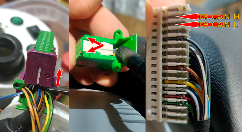
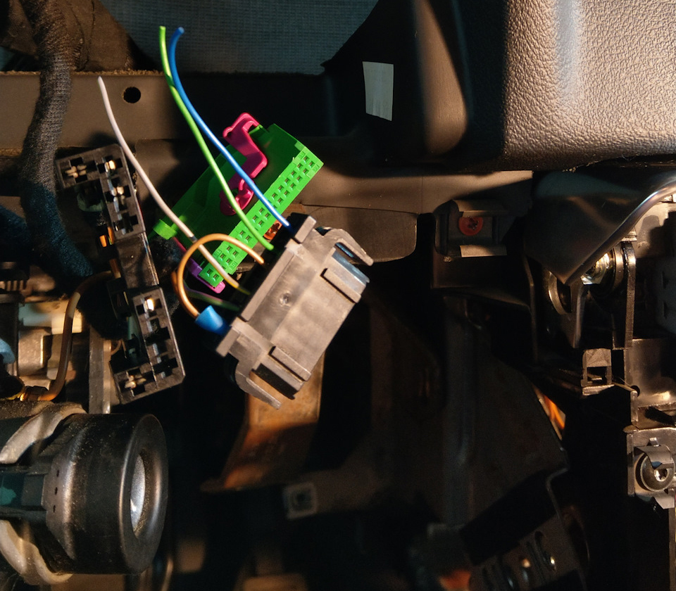
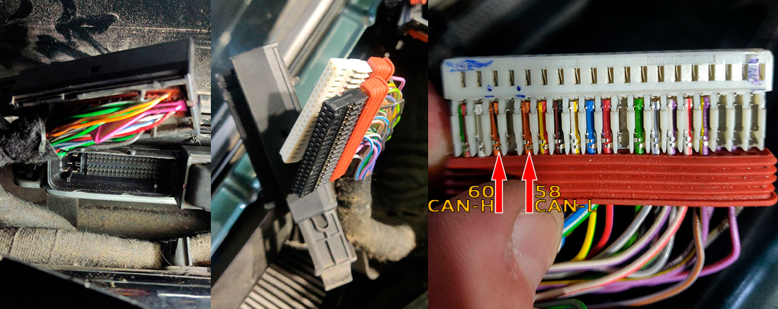
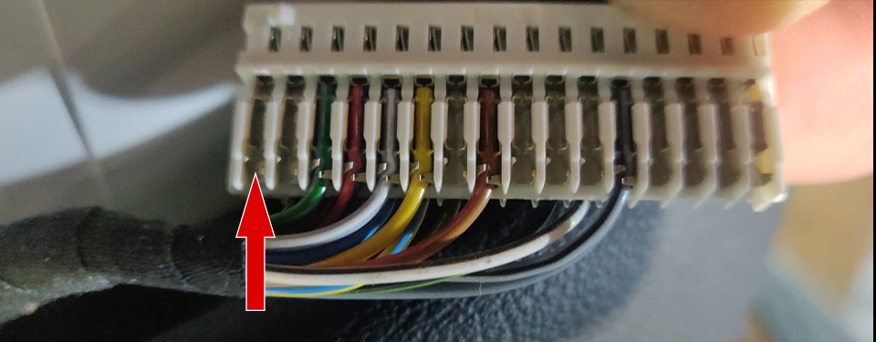
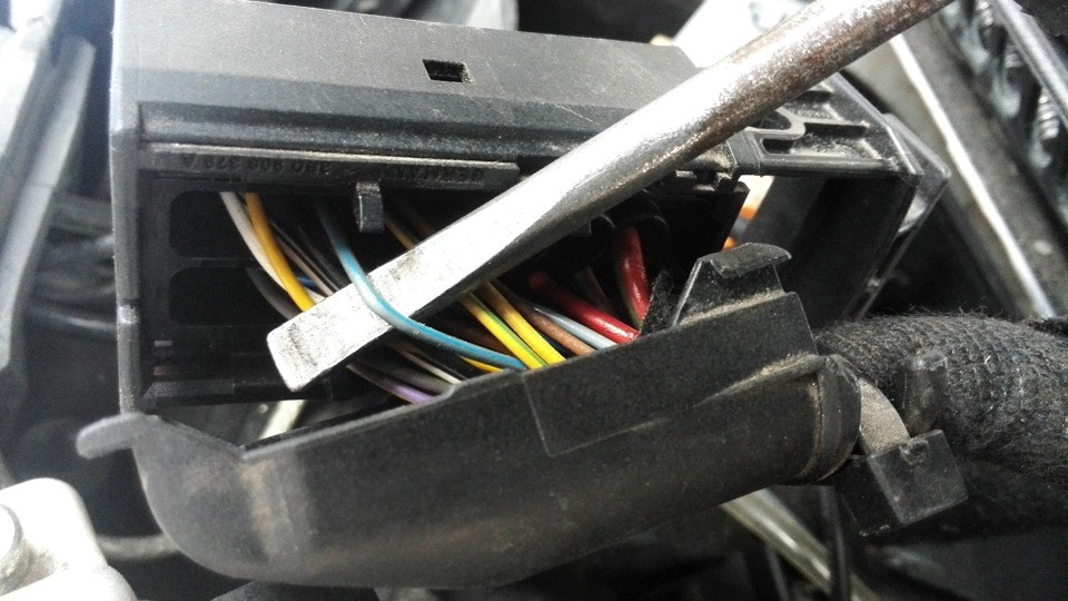
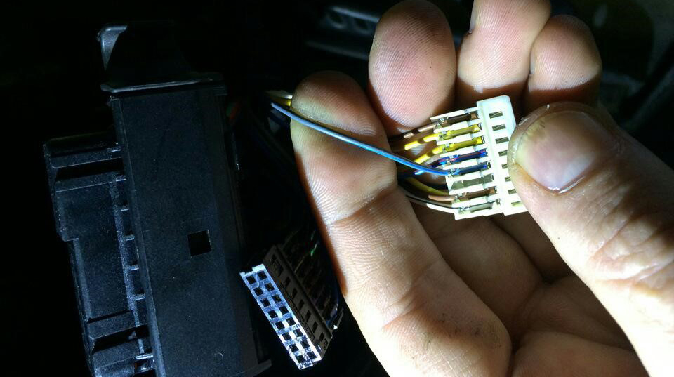
0.1 Check for CAN BUS wires in the green connector (pin18
and pin19).
If they are missing, add them, then do the cluster coding in
VCDS.
0.1. Нужно проверить наличие CAN BUS
проводов в зеленом коннекторе ( pin18 и pin19).
Если их нет, их нужно добавить, затем сделать кодирование
кластера в VCDS.
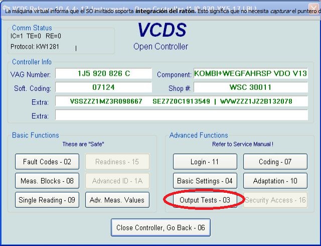
0.2. Cluster CAN-bus encoding
This cluster was coded to immo 2 at the can bus I have coded it to Channel
60: 01052 that's immo 3 and everything is working now
Channel 60: 1025 for manual gearbox, 1027 for automatic
You should check channel 62 in Cluster. If there is a zero the cluster won't
get any Infos on Can-Display. Same to channel 61 for Can Comfort and Channel
60 for Can Motor
If the dashboard will work correctly then you can do
the installation 3dMFD.
0.2. Кодирование приборки для работы CAN-bus
Этот кластер был закодирован на immo 2 на шине can, я закодировал его на
канал 60: 01052, это immo 3, и теперь все работает.
Канал 60: 1025 для МКПП, 1027 для АКПП
Нужно проверить канал 62 в Кластере. Если есть ноль, кластер не получит
никакой информации на Can-Display. То же, что и канал 61 для Can Comfort и
канал 60 для Can Motor.
Если
приборка будет работать правильно значит можно делать установку
3dMFD.
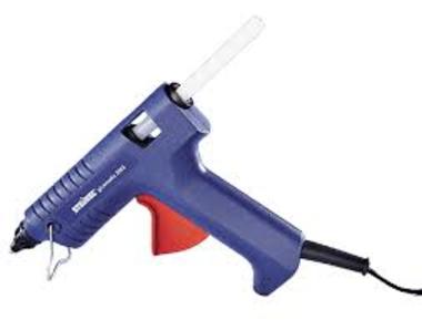
You will need:
Soldering iron 40W
Tin
Flux
Multimetr
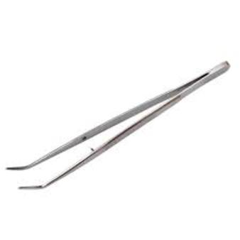
Tweezers
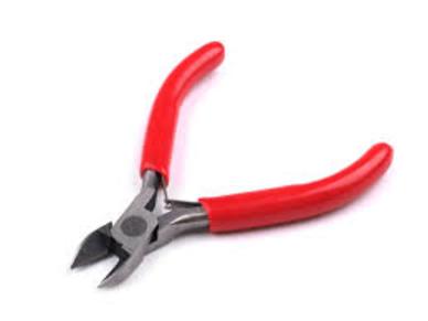
Nippers
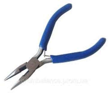
Pliers
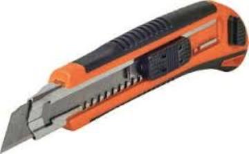
Knife
Thermocouples
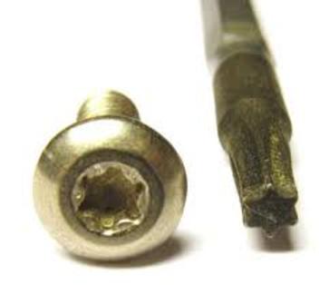
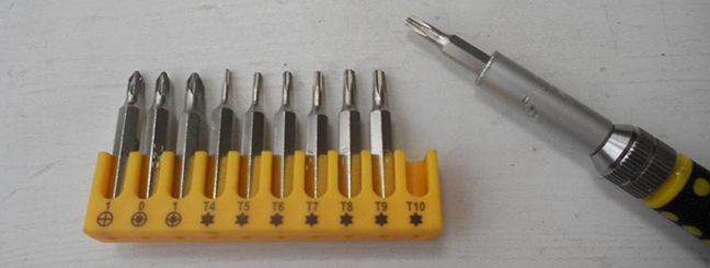
And screwdriver Torx T10
Safety
precautions
DO NOT!
ATTENTION!!!
When installing a color 3dMFD, there are 3 most important points.
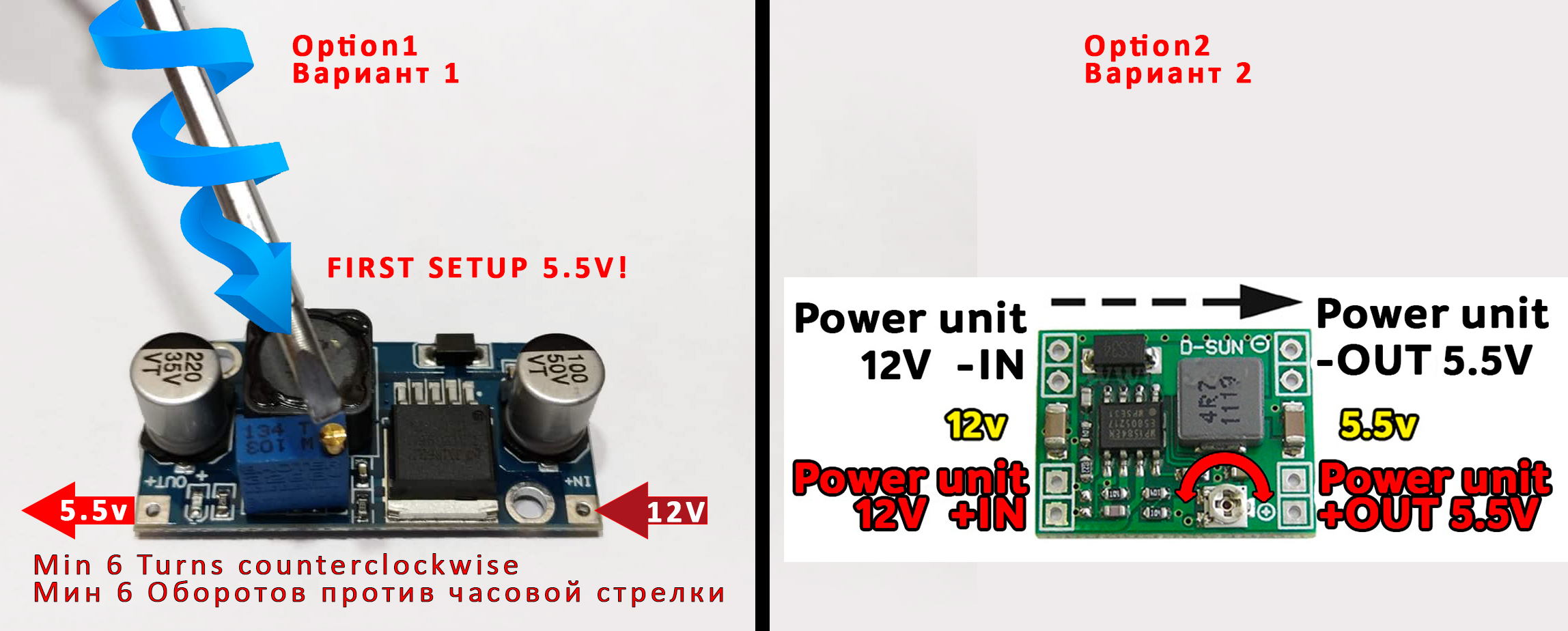
1. You need to
configure the power supply to 5.5v.
The MFD operates at a voltage of
5.5v.
When you connect the power supply to the MFD you should make
sure that the output of the contacts is
5.5v, otherwise it
will damage the processor! Paragraph
18
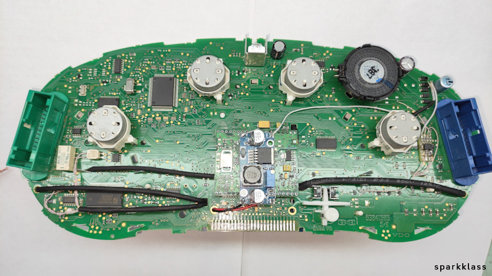
2. It is necessary to cut the
power tracks going to the pins
17,18,19.
then check that they are not voltage-free, you need to supply power
to the cluster
and check with a tester, one probe into the ground of the second to
each pin
17,18,19.
Should be 0v . 3. It is necessary to rinse all
soldering points. Install with extreme caution.
After soldering the wires, be sure to rinse the soldering
points with special flushing agents, or isopropyl alcohol.
During flushing, do not allow alcohol to get on the display
or under the display and its board!
При установке
цветного MFD есть 3 самых важных пункта:
1. Нужно настроить блок питания на 5.5в.
Модуль работает на напряжении
5.5в.
Кода вы подключаете блок питания к модулю,
вы должны убедиться в том, что на выходе контактов
напряжение
5.5в,
иначе это приведет к повреждению процессора!
2. Нужно перерезать дорожки питания,
идущие к пинам 17,18,19,
после чего проверить, чтобы на них не было напряжения. Для
этого нужно подать питание на приборку и проверить с помощью тестера,
один щуп в землю, а второй к каждому пину
17,18,19.
Должно быть
0в.
3. Нужно промыть все места пайки.
Устанавливать предельно осторожно.
После пайки проводов обязательно
промыть места пайки специальными промывочными средствами или
изопропиловым спиртом.
Во время промывки не допускать попадания
спирта на дисплей или под дисплей и его плату!
1. Disassemble the cluster.
1. Разбираем приборку
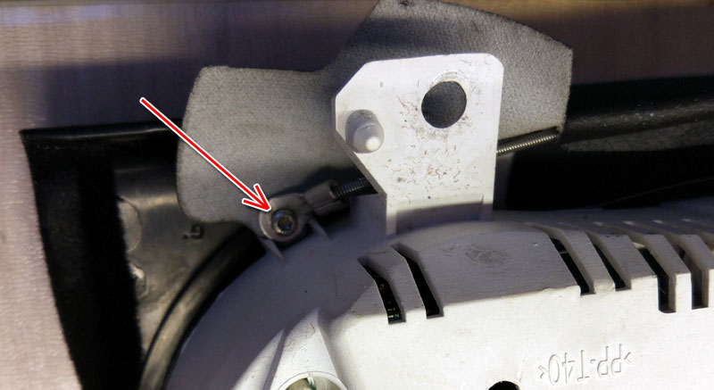
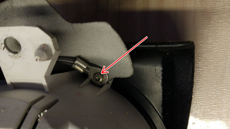
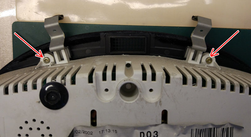
1.1 With a screwdriver torx T10, unscrew the two screws edges on the
rear of the instrument panel.
1.1.
Используйте отвертку ТОРКС Т10
Bend all the latches and neatly remove the front of the case (with
glass).
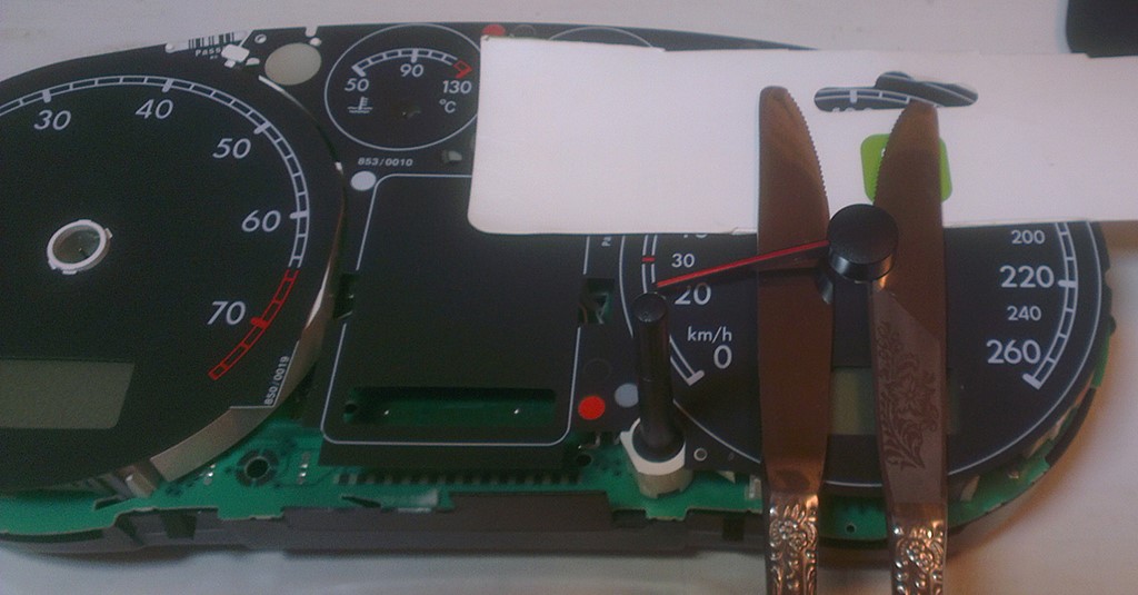
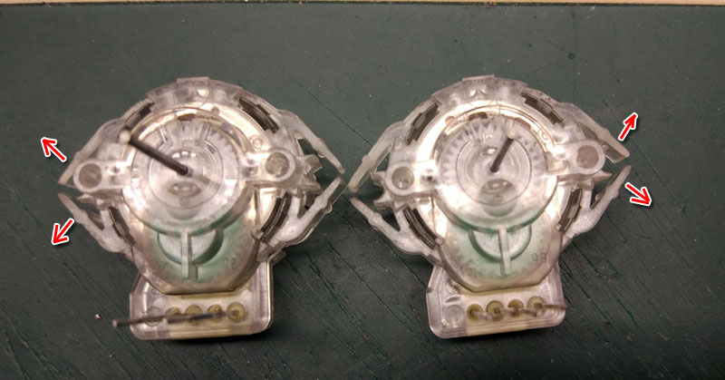
1.2 Remove the needles.
There are 2 ways to do it:
scroll counter-clockwise
and simultaneously pull it to yurself or
using using non sharp butter knives or spatula,
shoot the arrows from their shafts.Its
better to put paper between the knives and the base of the
device to avoid damaging it.
Pull the arrows up to yourself.
1.2 Удалите
стрелки. Сделать это можно двумя способами:
Крутите против часовой стрелки и
одновременно потяните
на себя.
Или используя неострые ножи для масла
или лопатку. Лучше положить бумагу между ножами и основанием устройства,
чтобы не повредить его. Вытяните стрелки к себе.
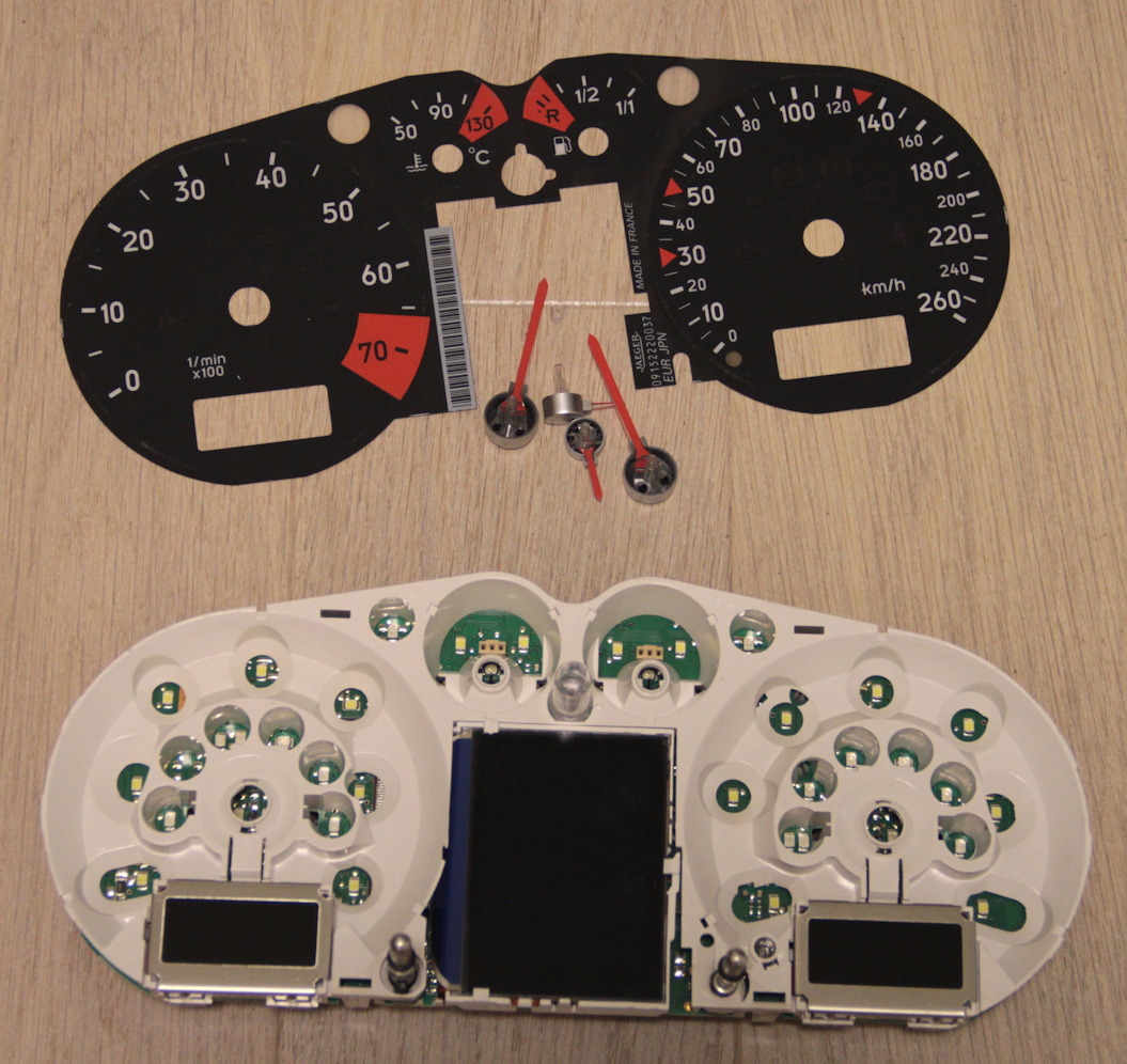
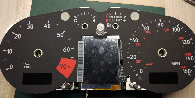
1.3.Then
remove the substrate. Удалите шкалы.
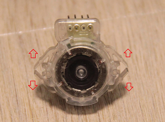
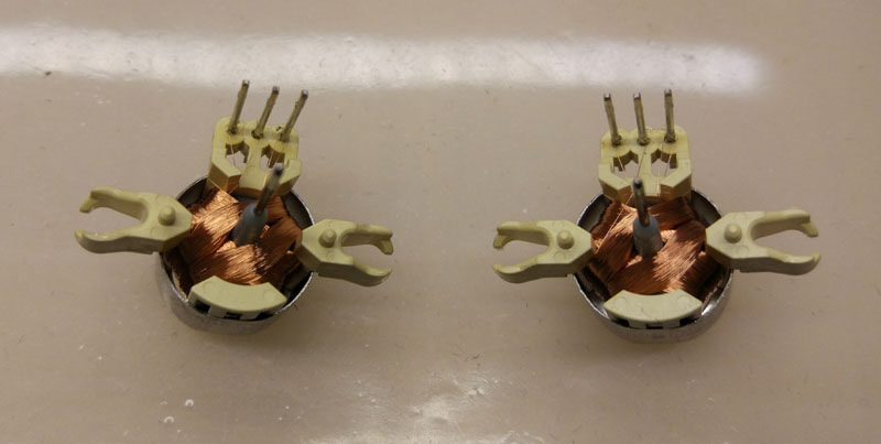
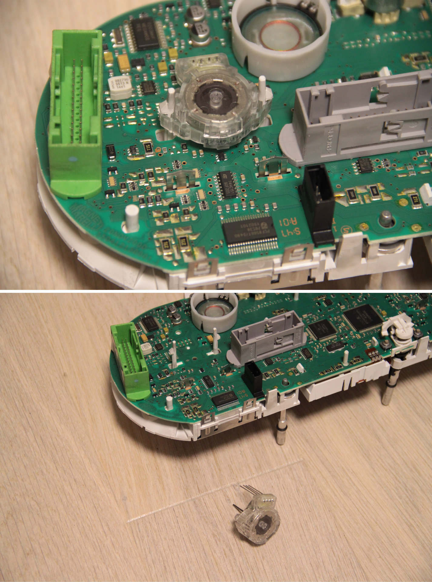
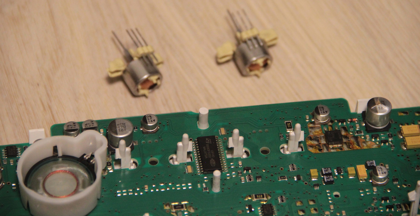
1.4. Remove the speedometer and tachometer motors.
Снимите двигатели спидометра и тахометра.
1.4.
Remove white plastic (noFIS)
Удалите белый пластик
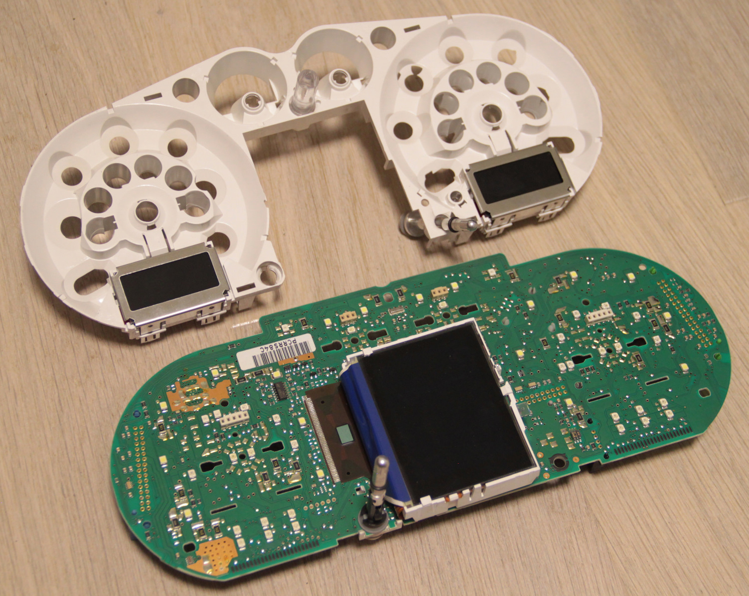
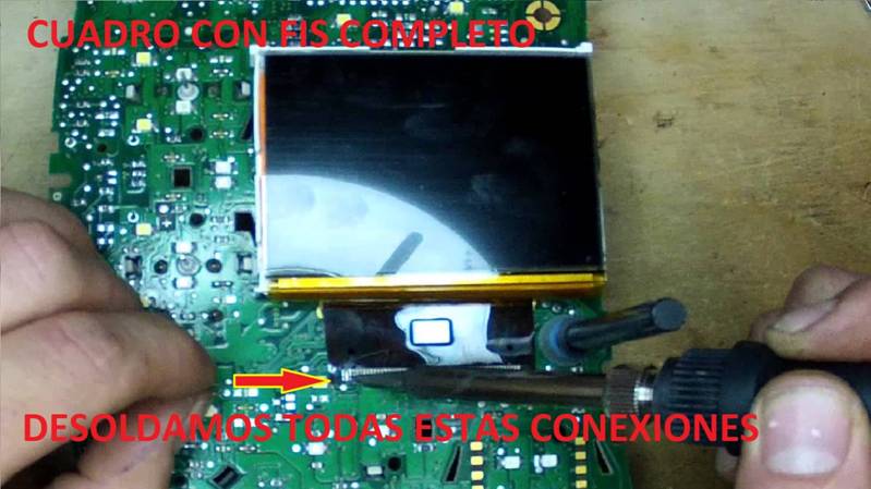
1.5.1.
Remove display(fullfFIS)
It is necessary to remove the display by gently heating the loop
with which it is soldered to the board,
do not tear off the display as you can damage the dashboard board.
1.5.
Удалитедисплей
Снимать дисплей необходимо, аккуратно нагревая шлейф, которым он
припаян к плате,
не отрывайте дисплей, так как вы можете повредить приборную панель.
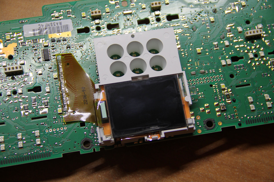
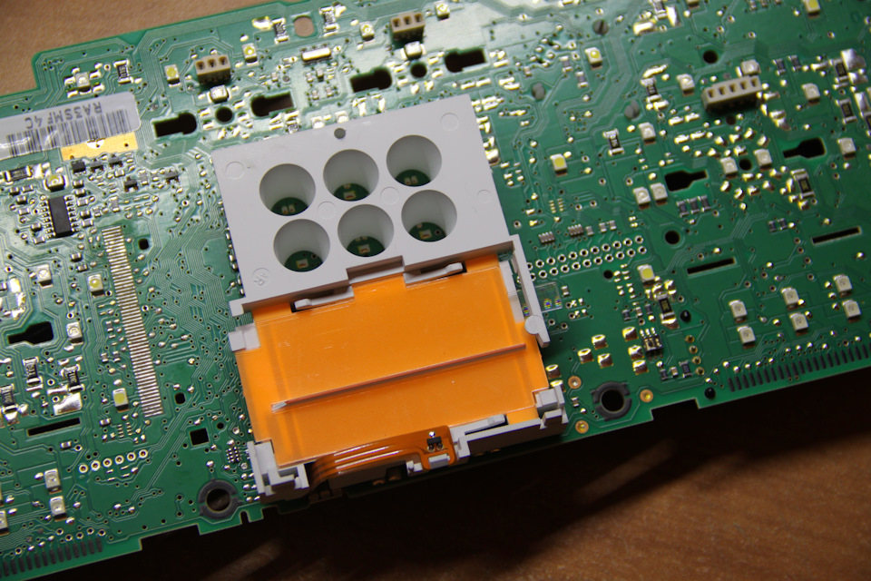
1.5.3. Remove temperature sensor.
There is a temperature sensor in a fullFIS clusters. It can be
removed with a soldering iron
or simply cut off the sensor tape in any convenient place, so that
it does not interfere later.
1.5.3. Удалите датчик температуры.
В кластерах fullFIS есть датчик температуры. Снимается паяльником.
или просто обрежьте сенсорную ленту в любом удобном месте, чтобы
потом она не мешала.
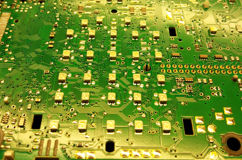
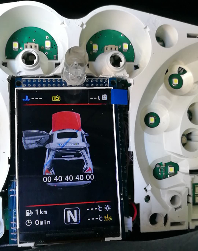
1.6.Then you need to remove all the LEDs that are
were under the standard display
1.6.
Затем нужно убрать все светодиоды, которые были
под штатным дисплеем.
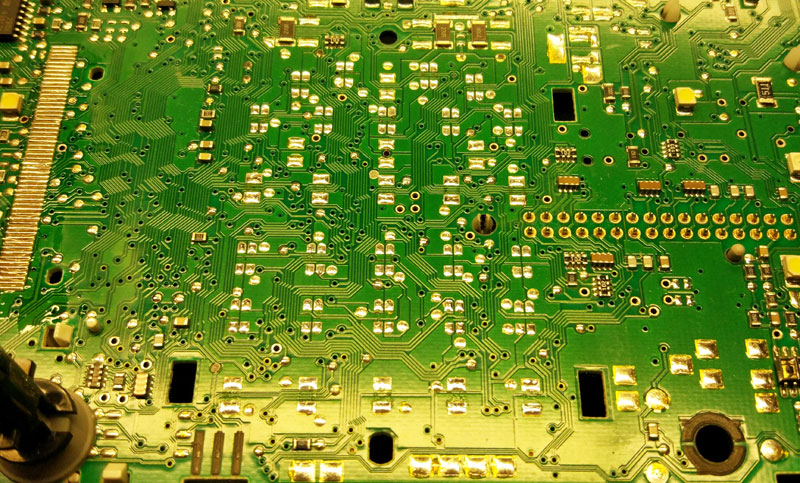
1.8. We make sure
that there are no jumpers made of tin.
After removing the LEDs, clean the board from tin residues and rinse
with alcohol.
1.8. Следим за тем,
чтобы не было перемычек из олова и.
После снятия светодиодов очистите плату от остатков олова и промойте
спиртом.
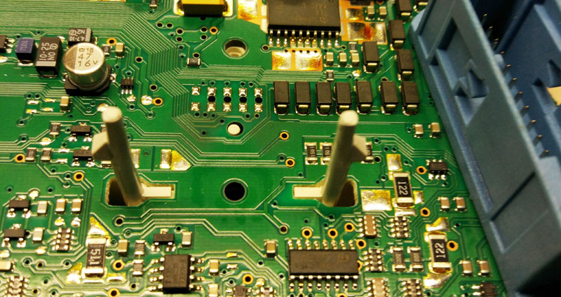
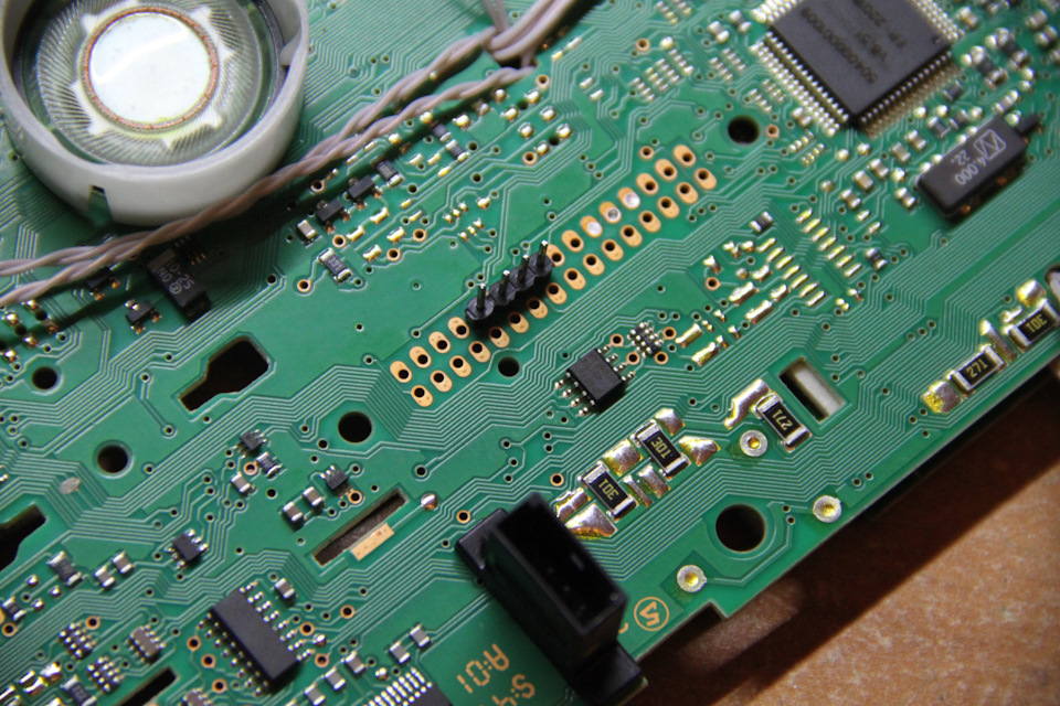
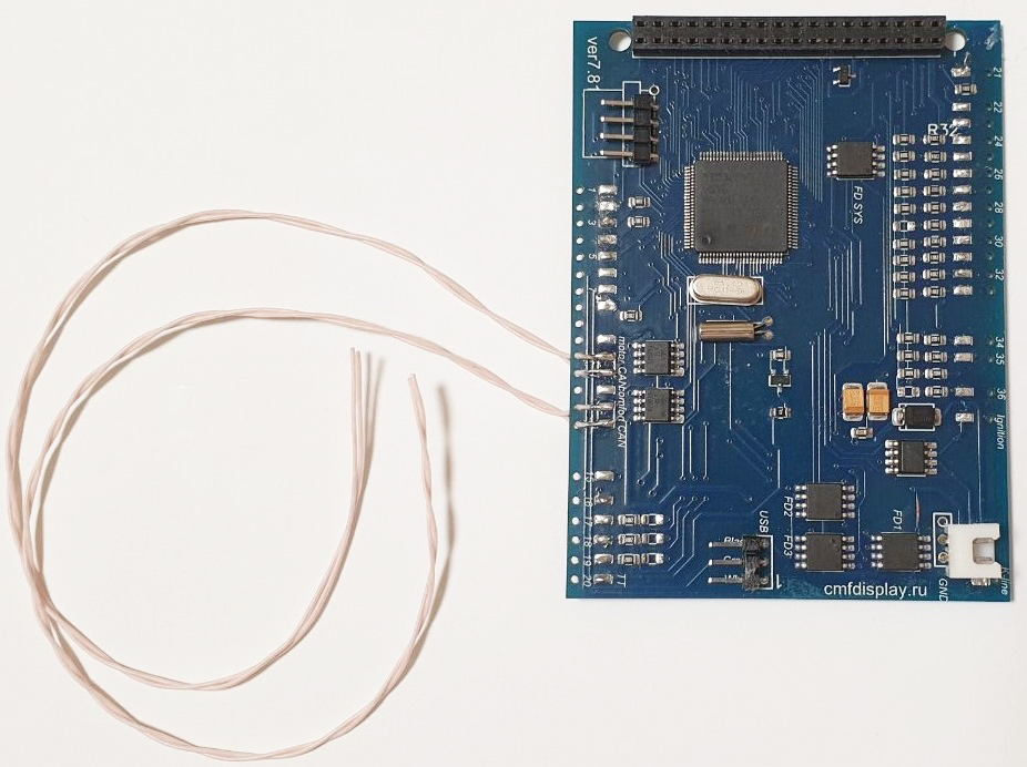
1.9 Controls:
To control the 3dMFD you need to add the missing pins, you can use the stock
points for this.
1.9.
Управление:
Для упраления 3dMFD нужно
добавить недостающие
пины, для этого можно использовать штатный точки.
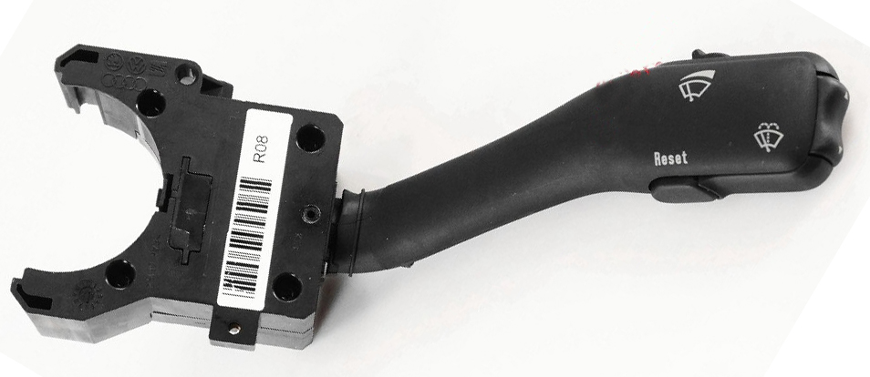
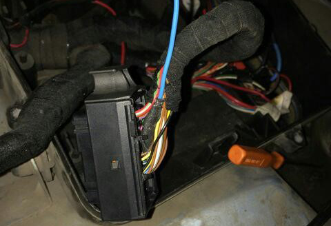
Connecting the steering wheel switch:
switch connector / dash connector
1 - 17 dashboard green connector UP
2 - 18 green dashboard connector DOWN
3 - GND blue dashboard connector
4 - 19 dashboard green connector
RESET
1.10.
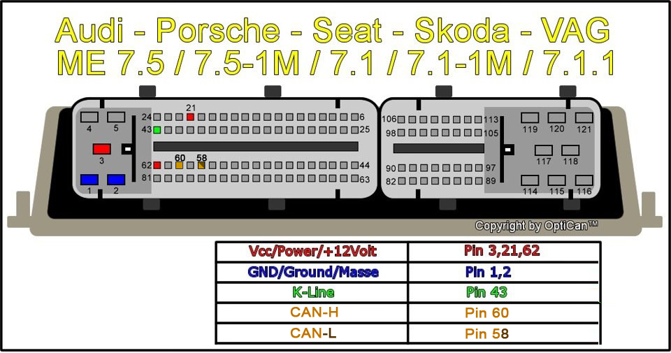
1999-2000 model year may have not wires ofCAN-bus Motor
11pin 3dMFD -> to 18pin green
connector of cluster -> ECU 60 pin CAN H
10 pin 3dMFD -> to 19pin green connector of cluster -> ECU
58 pin CAN L
Audi TT 1.8T
(98-99) AJQ add can-motor
10 pin MFD -> green 19 -> CAN L (motor)-> pin ECU 77L
11pin MFD -> green 18 -> CAN H (motor)-> pin ECU 79H
1.10.
1999-2000 модельный год иногда не имеет проводов
CAN-bus Motor
11pin 3dMFD -> to 18pin green
connector of cluster -> ECU 60 pin CAN H
10 pin 3dMFD -> to 19pin green connector of cluster -> ECU
58 pin CAN L
Audi TT 1.8T
(98-99) AJQдобавить
can-motor
10 pin MFD -> green 19 -> CAN L (motor)-> pin ECU 77L
11pin MFD -> green 18 -> CAN H (motor)-> pin ECU 79H
1.11. Cluster CAN-bus encoding
This cluster was coded to immo 2 at the can bus I have coded it to Channel
60: 01052 that's immo 3 and everything is working now
Channel 60: 1025 for manual gearbox, 1027 for automatic
You should check channel 62 in Cluster. If there is a zero the cluster won't
get any Infos on Can-Display. Same to channel 61 for Can Comfort and Channel
60 for Can Motor
1.11.
Кодирование приборки для работы CAN-bus
Этот кластер был закодирован на immo 2 на шине can, я закодировал его на
канал 60: 01052, это immo 3, и теперь все работает.
Канал 60: 1025 для МКПП, 1027 для АКПП Нужно проверить канал 62 в Кластере. Если есть ноль,
кластер не получит никакой информации на Can-Display. То же, что и канал 61
для Can Comfort и канал 60 для Can Motor.
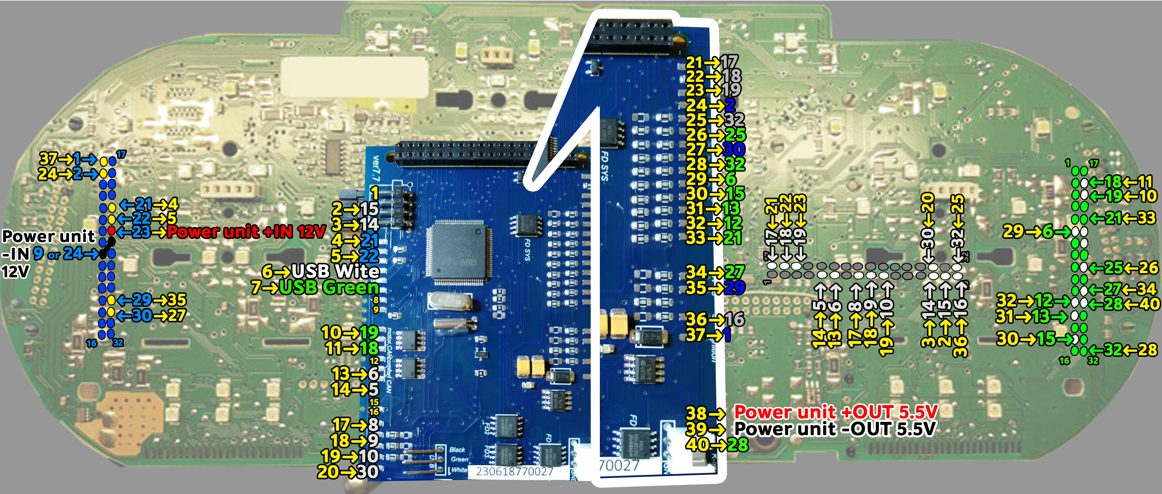
2. Installation / Установка
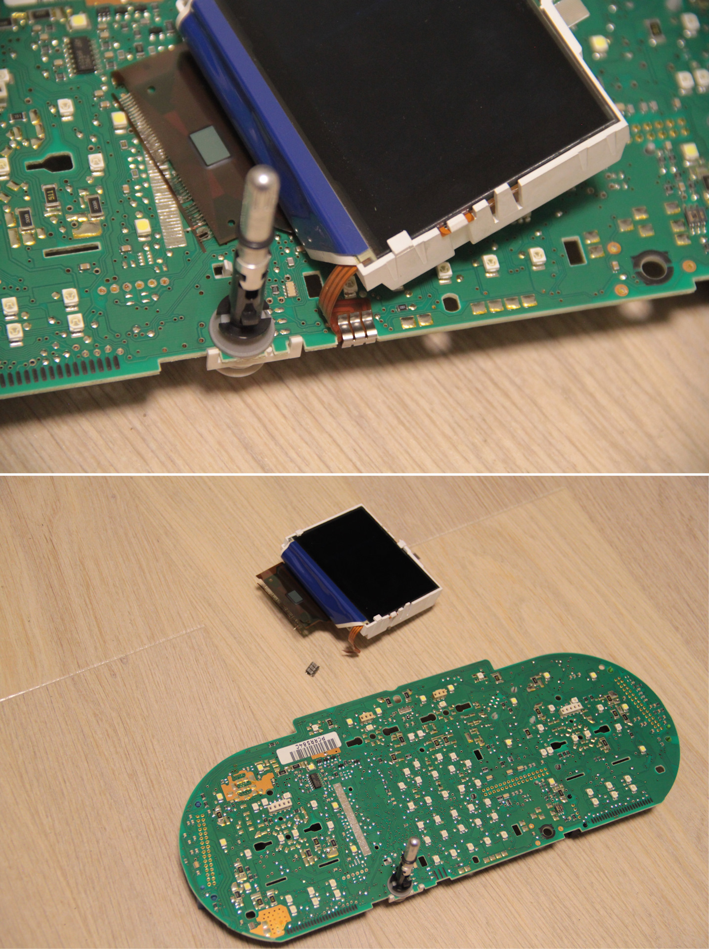
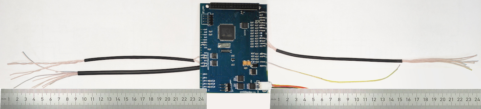
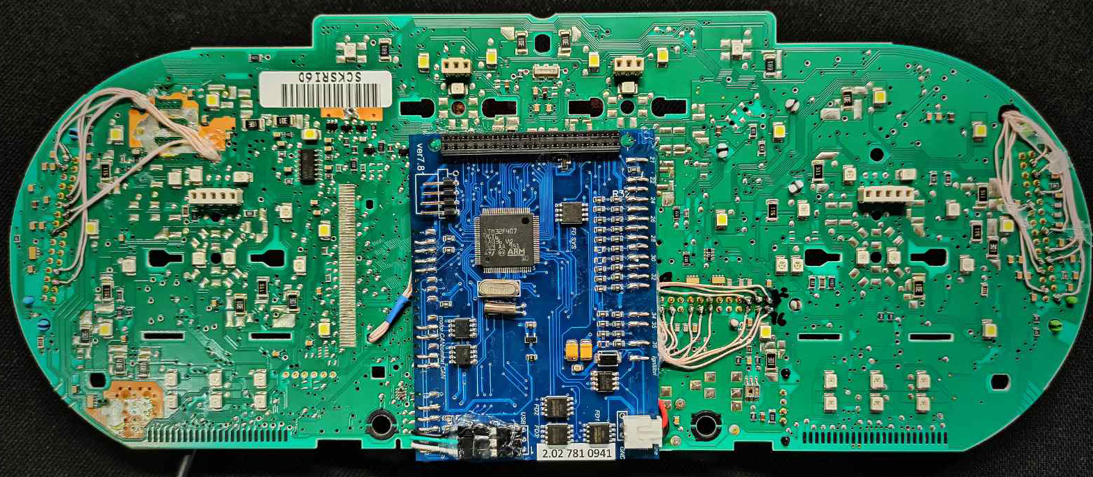
2.1.
Remove LCD board from motherboard and Stretch the wires from MFD
motherboard to the blue and green connectors through the holes in
the cluster`s board.
2.1. Снимите ЖК-дисплей и протяните провода
от материнской платы MFD к синему и зеленому разъемам через
отверстия в плате кластера.
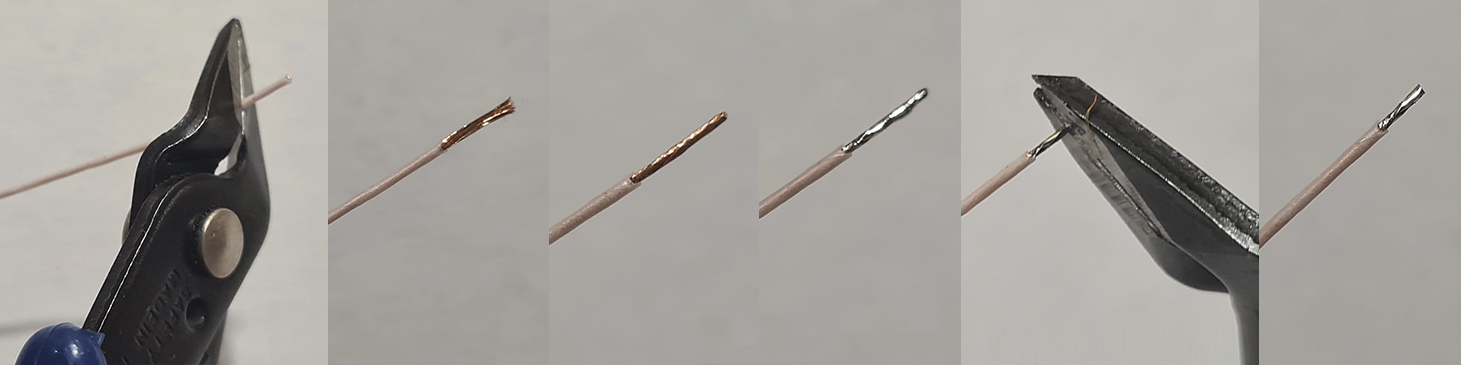
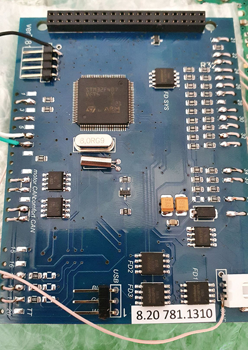
2.2 Start
to soldering wires according to the table. Wires should be cleaned
from Isolation, twisted and tin plated.
2.2 Приступаем к пайке проводов по таблице. Провода должны быть
очищены от изоляции, скручены и залужены.
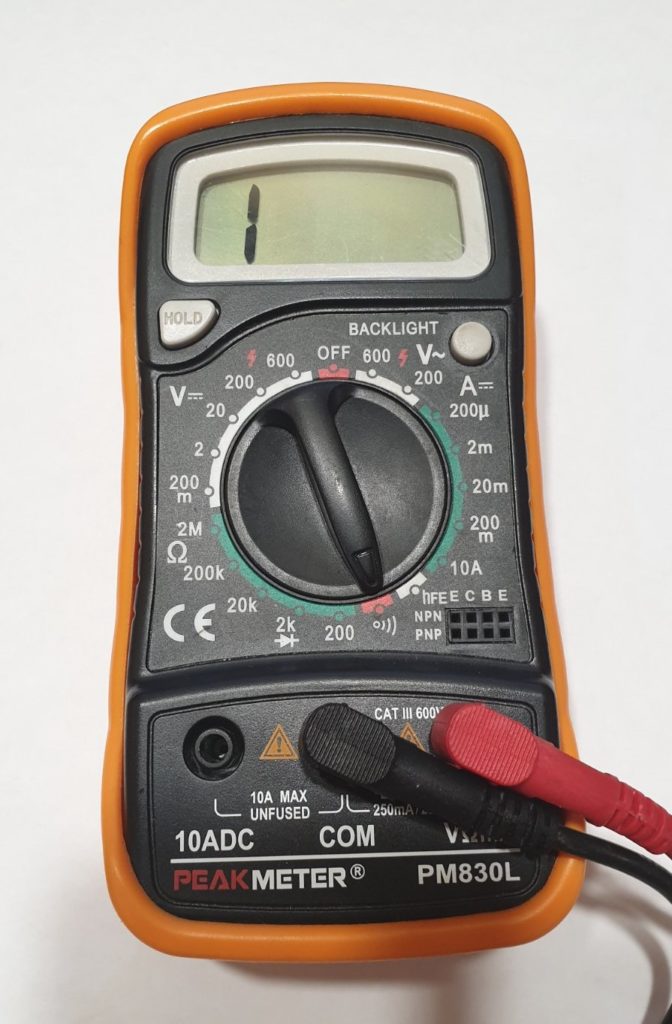
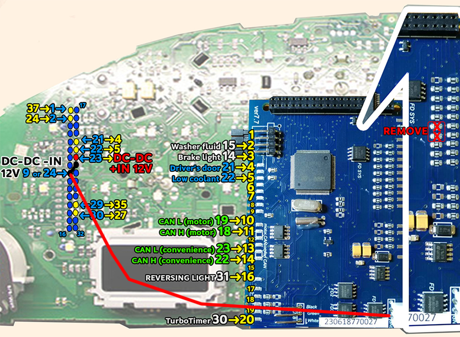
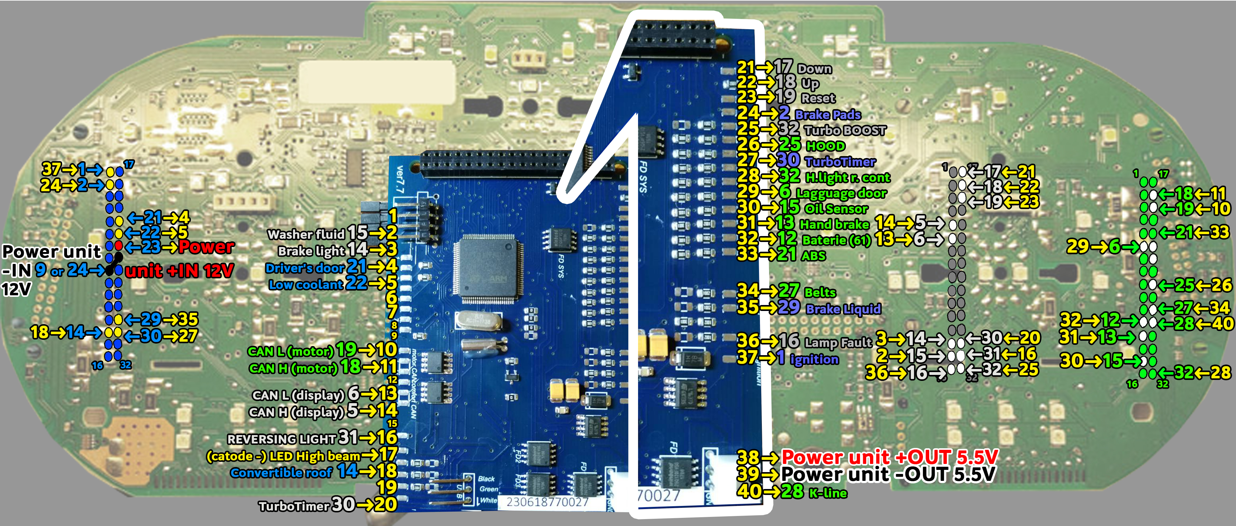
2.3
Take the multimeter, set it to Diode (Ring) mode.
Using multimeter and wiring diagram, find the wires
you need and solder them to the connector pins.
2.3 Используйте мультиметр,
установите его в режим диода (прозвонка)и схему подключения, найдите нужные провода и припаивайте
их
к контактам разъемов.
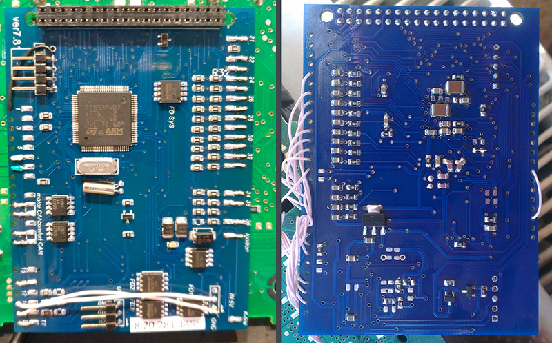
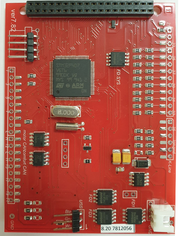
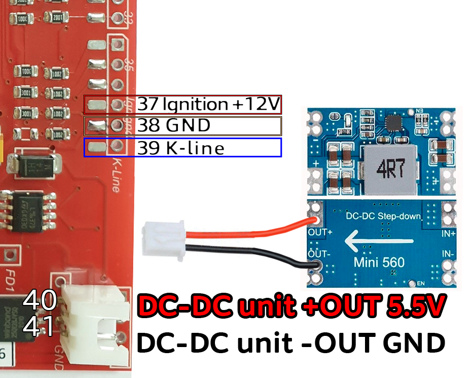
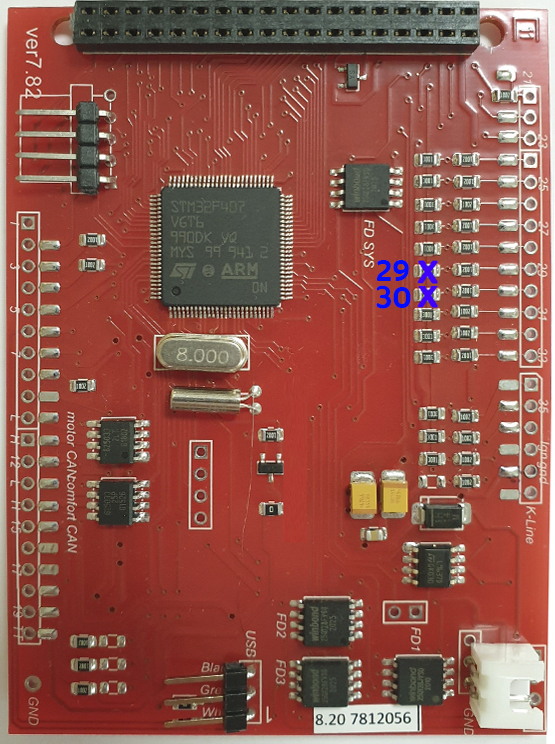
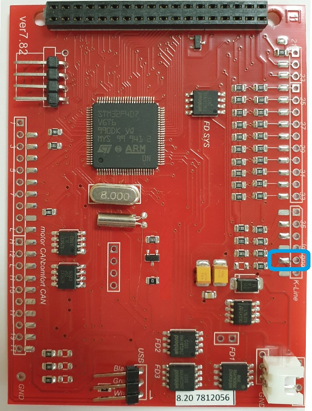
2.3.1 The
new board revision 7.8.2 has minor differences. 37 pin ignition 38 pin GND 39 pin K-line
Новая ревизия
платы 7.8.2 имеет небольшие отличия. 37 пин зажигание
38 пин GND 39 пин К-линия
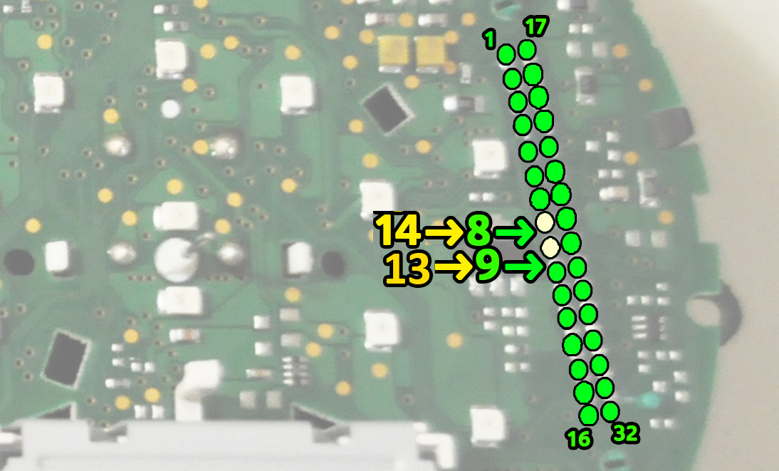
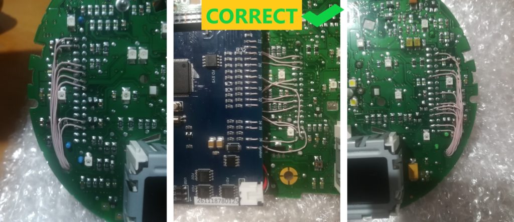
2.4. Twist in a spiral
CAN-bus connection wires. CAN-bus Comfort — 8, 9 pins of Green
connector;
CAN-bus Motor — 19, 20 pins of Green connector.
2.4 Обязательно скручивайте в спираль
провода, который вы будете подключать к CAN-шине. CAN-шины коомфорта - 8,
9 контактов зеленого разъема; CAN-шины двигателя - 19, 20
контактов зеленого разъема.
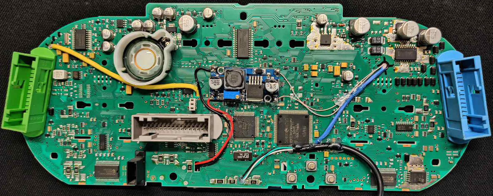
2.5.
There are 2 ways to connect CAN bus wires. Choose what is
convenient for you.
2.5.
Есть два варианта подключения проводов CAN-шины.
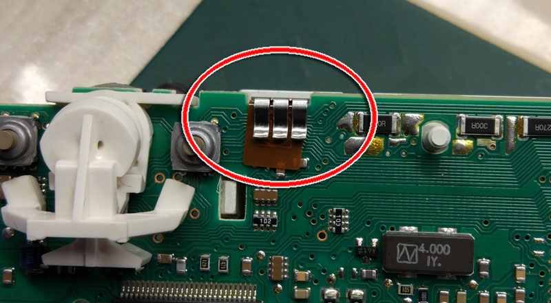
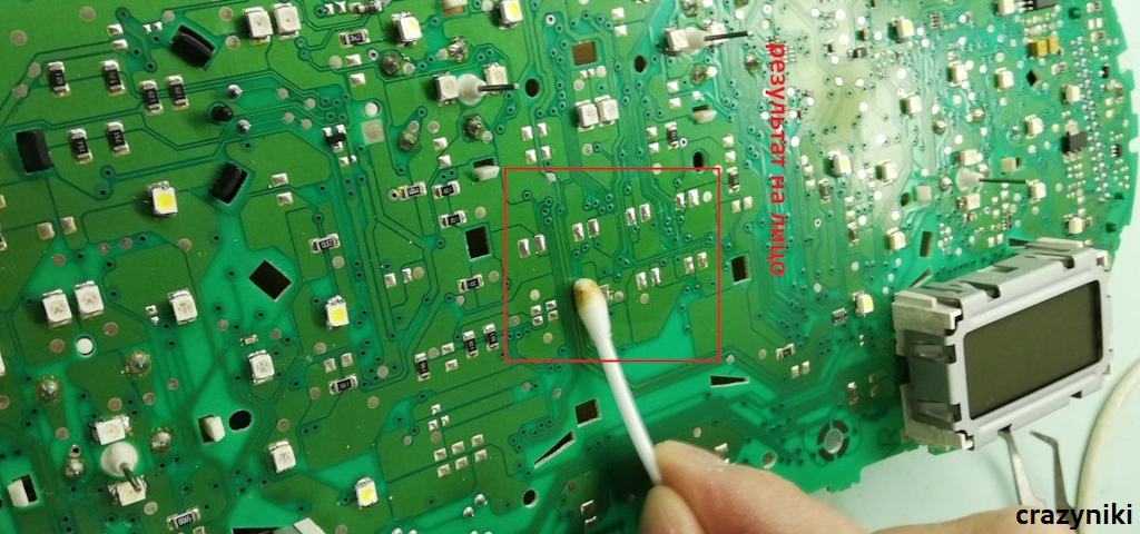
1-st way: solder the wires to to the pins of the green connector
1-й вариант подключить провода к пинал разъема
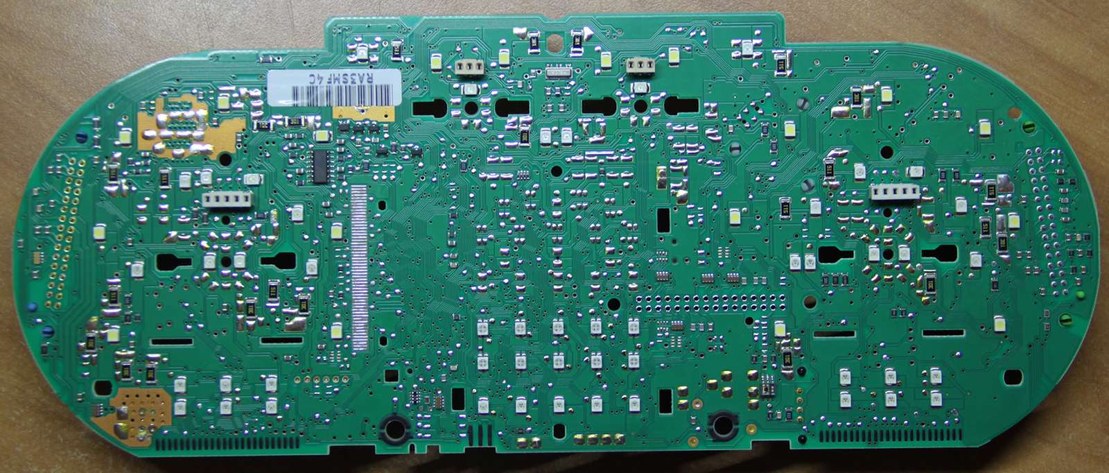
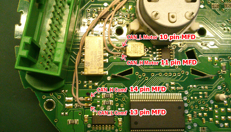
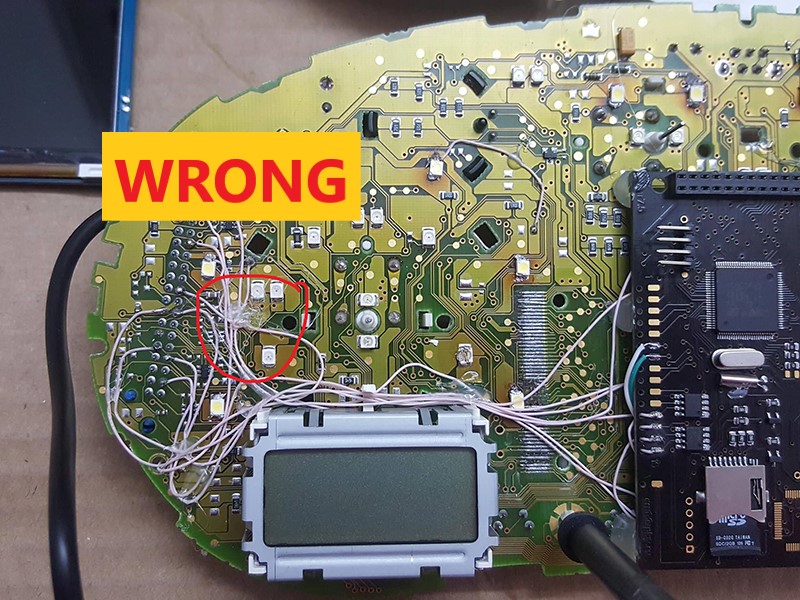
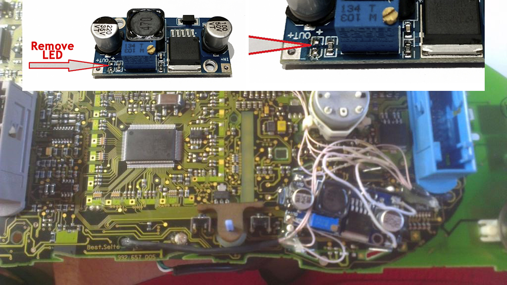
2-nd way: solder the wires to the points, indicated in the photo
2-й вариант подключить провода к точкам на тыльной стороне платы приборки.
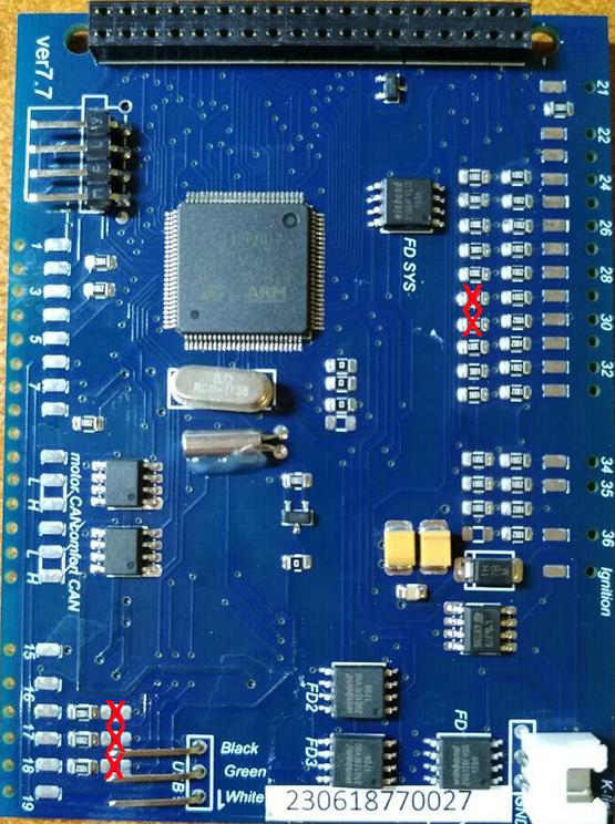
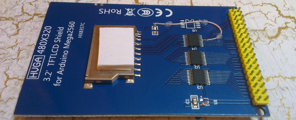
2.6.
Important! Remove the resistors from the 3dMFD board as shown
in the picture.
2.6. Важно!
Снимите резисторы с платы 3dMFD, как показано на рисунке.
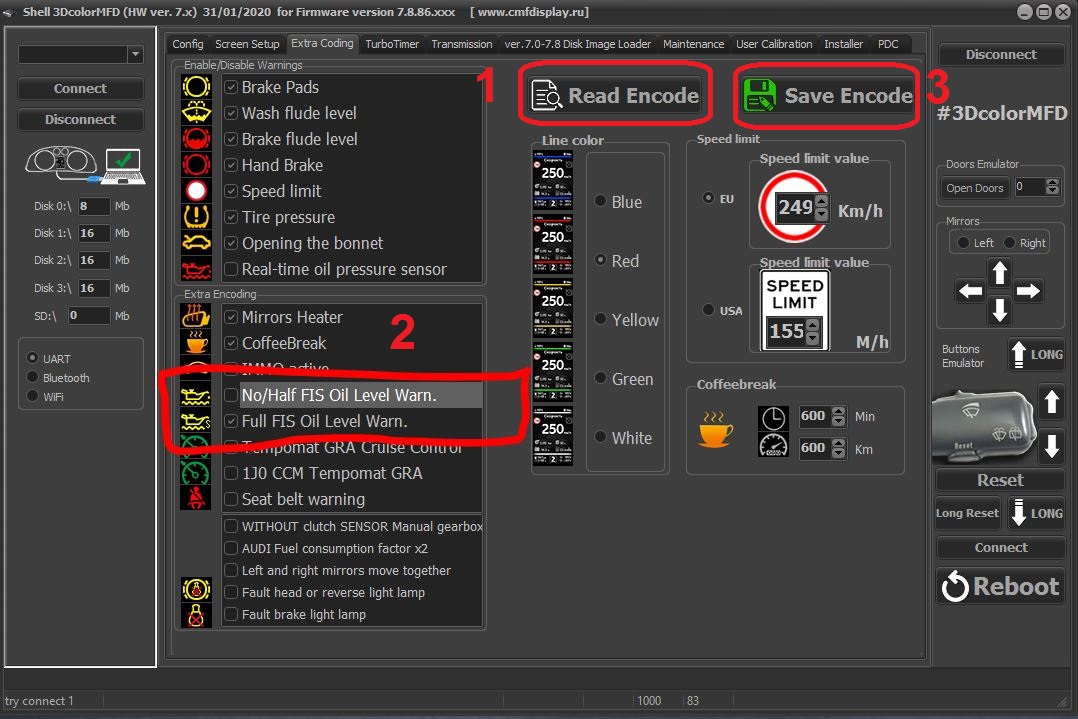
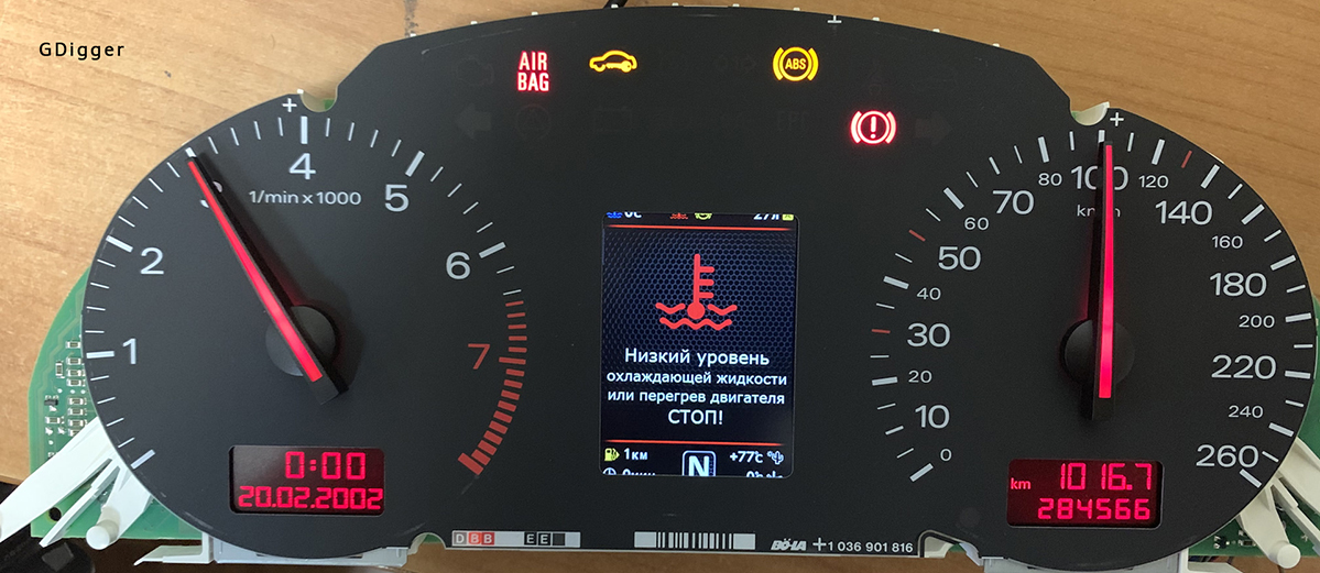
After installation, you need to connect MFD to the Shell program
and configure the low oil warning for the FullFIS cluster.
После установки необходимо подключить MFD к программе Shell и
настроить предупреждение о низком уровне масла для кластера FullFIS
как показанно ниже на картинке.
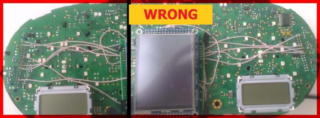
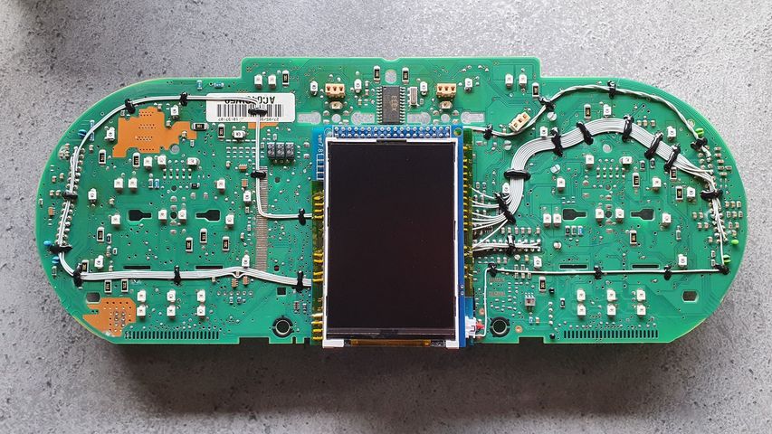
2.7. Lay the
wires in such a way that they do not interfere with the installation of
white Light diffuser.
2.7. Провода следует тянуть с тыльной
стороны или, как показано выше,так чтобы
при сборке приборки
провода не мешали.
2.7. Wires should be pulled from the back sideOr
as shown above, so they do not interfere with the assembly of the
device.So
it's not right!
2.7. Провода следует тянуть с тыльной
стороны или, как показано выше,так чтобы
при сборке приборки
провода не мешали.
Attention!
2.8. Before installing the power supply, you need to solder
the wires to it
contacts+IN-INand
+OUT-OUT,
then apply a current of 12V to +IN-IN,
andconnect
the+OUT-OUTwires
to the tester.
Now we need to adjust
the output current.Using
a small flat screwdriverslowly
rotate the special metal knob (figure 1 in the picture.) Clockwise
Arrow,
until, at us on the tester will not appear 5,5v in an output
voltage.
Next we
place the power supply unit on the back side, we bring to its
contacts the wires from the
blue connector.
9
pin of blue
GND connector is
connected to the e-INon
the power supply board. 23 pin of blue +12V connector
is connected to+INOn
the power supply board,
ВНИМАНИЕ!
2.8. Перед установкой блока питания
необходимо припаять к нему провода контакты + IN - IN и + OUT - OUT,
затем подайте ток 12 В на + IN - IN и подключите провода + OUT - OUT
к тестеру.
Теперь нам нужно настроить выходной ток. С помощью небольшой плоской
отвертки медленно поверните специальный винт (цифра 1 на рисунке) по
часовой стрелке много раз, до тех пор, пока, у нас на тестере не
появится +5,5v в выходном
напряжении. Далее размещаем блок питания с тыльной стороны, подводим
к его контактам провода от зеленого разъема.
9
контакт синего разъема -
GND
подключен к разъему e-IN на плате блока
питания. 23контакт синего разъема
+12V
подключен к + IN на плате блока
питания,
2.8. Connect
+OUTConnects
to 38 pin MFD
-OUTConnects
to 39 pin MFD
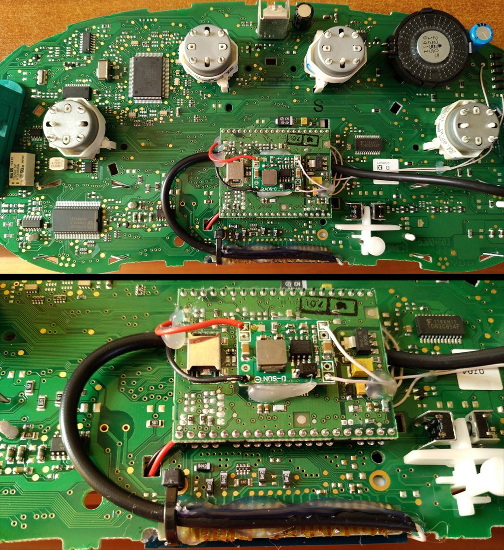
Choose the place of
installation of the power supply so that during assembly it does not
interfere.Here
are the possible
2.6. Соедините
+ OUT Подключается к 38-контактному МФД
- OUT подключается к 39-контактному MFD
Место установки блока питания выбирайте так, чтобы при сборке
провода не мешали и не передавливались.
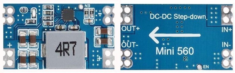
This type of DC-DC converter is
already set to 5.2V
Этот тип DC-DC конвертер уже настроен
на 5.2В
After wiring, lay it so that they do not interfere with further
assembly.Needto
call all contacts and check on the table to avoid confusion
anywhere.
После прокладки проводов необходимо
прозвонить с помошью мультиметра все контакты и проверить по таблице,
чтобы нигде не было ошибки
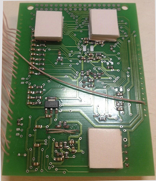
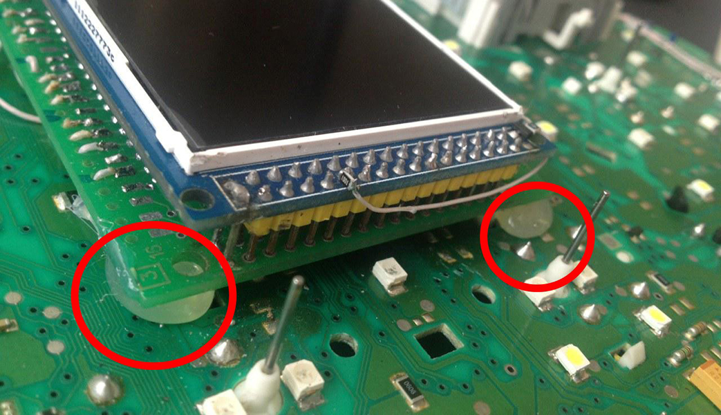
Attention!
For reliable operation of3dMFD , it is imperative to make an
additional GND connection as shown in the photo
Внимание!
Для надежной работы обязательно дужно сделать дополнительное
подключение GND как показанно на фото
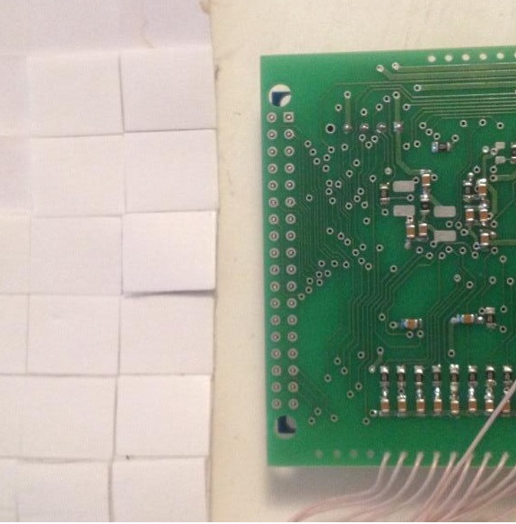
3. We take
double-sided adhesive tape on a foamy basis, cut the squares 1cmX1cm.
3. Берем двусторонний скотч и вырезаем квадраты 1см Х 1см.
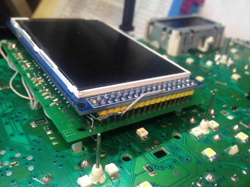
3.1. We collect these
squares in 3 floors.
3.1. Собираем
скотч в 3 слоя.
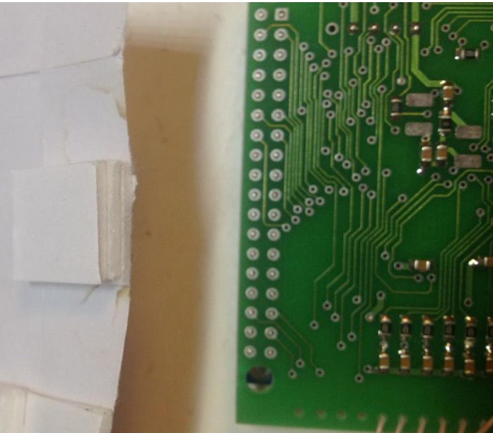
3.2. And we place it on the
3dMFD board, the height of the adhesive tape should be enough so
that the 3dMFD board does not touch the cluster board.
3.2. И
размещаем на плате 3dMFD, высоты скотча
должно быть достаточно, чтобы плата 3dMFD
не касалась платы приборки.
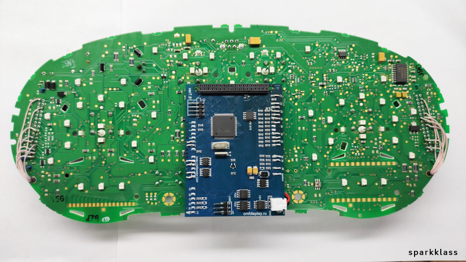
3.3. Place the module so that it is placed in the window of
the device
3.3. Разместите модуль так, чтобы он находился в оконе маски
приборки.
3.4.
For greater reliability, when the module is already installed on the
board,
and you calibrated it in the window so
that there were no distortions, it is better to fix it.
Its hot glue along the edges of the module.
3.4. Для большей надежности, когда модуль
уже установлен на плате, а вы откалибровали дисплей так чтобы не
было перекосов, вы можете зафиксирвать палту
3dMFD горячим клем по краям модуля. не нужно заливать
полностью всю плату в 2 -3 точках будет достаточно.
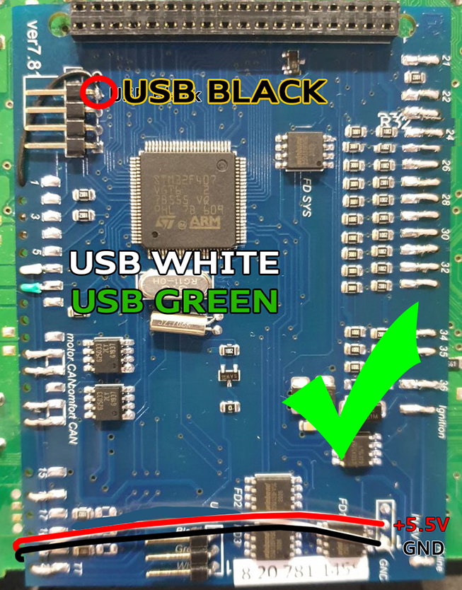
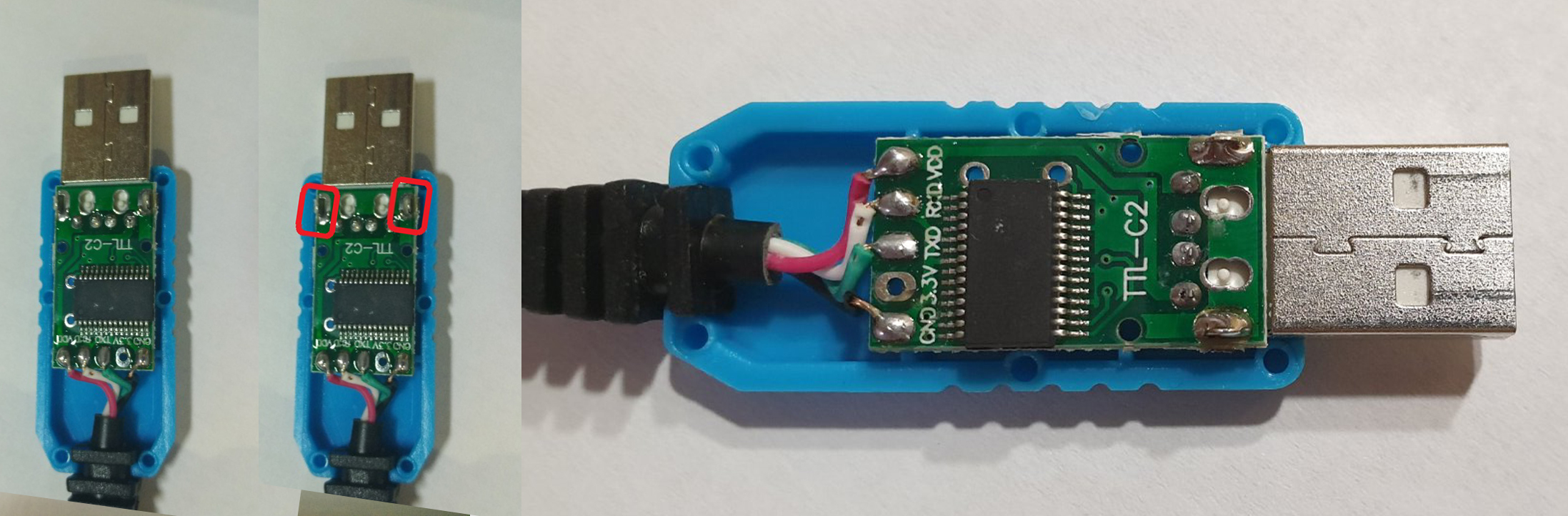
4. The USB
cable should be fixed with glue.
Red USB wire
do not use, cut it off.
4. Кабель
USB следует закрепить клеем. Красный провод USB не
используется.
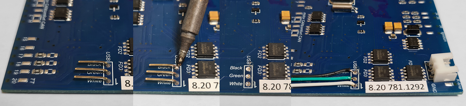
4.1.
1-WAY
of USB connection
4.1. 1-Й
вариант подключения
USB
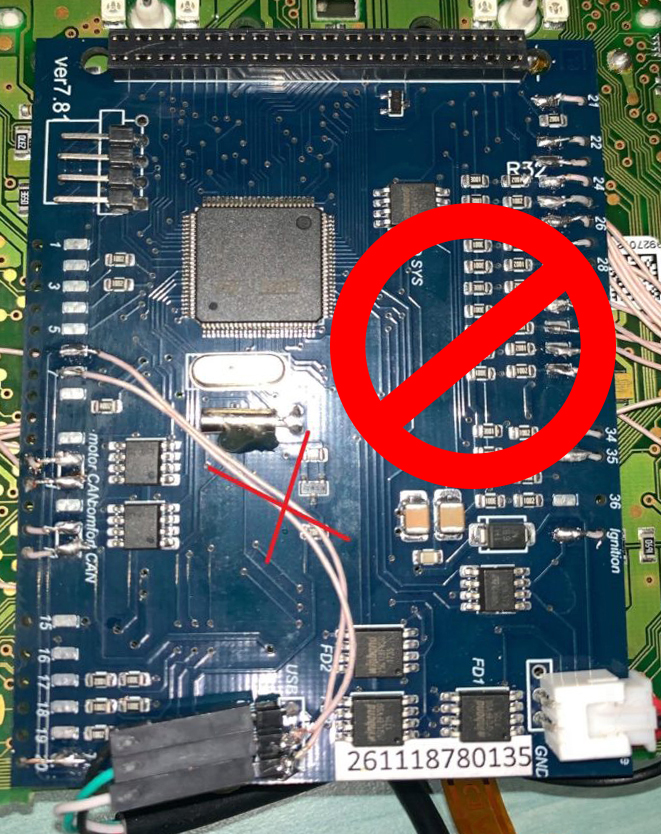
4.1.
WRONG-WAY
of USB connection
4.1.
Неправильный вариант подключения
USB
4.1.
2-WAY
of USB connection
4.1.
2-Й вариант
подключения USB
4.2.
OpenUSB
And solder
the metal ears marked in red.
4.2. Откройте
USB и припаивайте металлические уши отмеченные красным
5.
Before installing the display, you need to glue double-sided
adhesive tape into three layers on the back of the display to lock
the display.
Attention, you do not need to attach
modules to the board!
It is enough simply to remove an additional support from a
double-sided adhesive tape without removing the protective layer
from the side of the module board.
5. Перед
установкой дисплея нужно приклеить двухсторонний скотч, для того
чтобы создать дополнительную опору Внимание!
Приклеивать дисплей к плате 3dMFD не
нужно!
Достаточно просто снять дополнительную опору с двустороннего скотча,
без снятия защитного слоя со стороны платы 3dMFD.
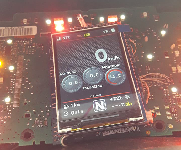
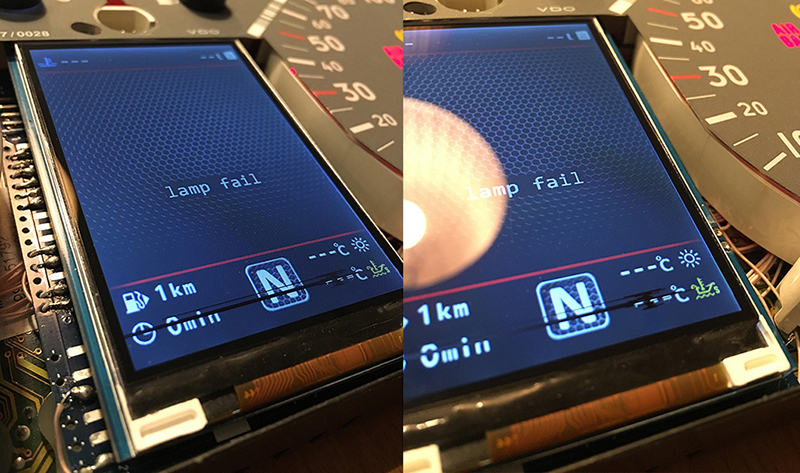
6. After you
solder the wires and set the display to its place, you need to
test the 3dMFD
performance in the car to make sure everything is properly installed
and working well.
6. После того, как вы припаяли
все провода и установите дисплей на место, dам
необходимо протестировать работу 3dMFD в
автомобиле, чтобы убедиться, что все правильно установлено и
работает нормально.
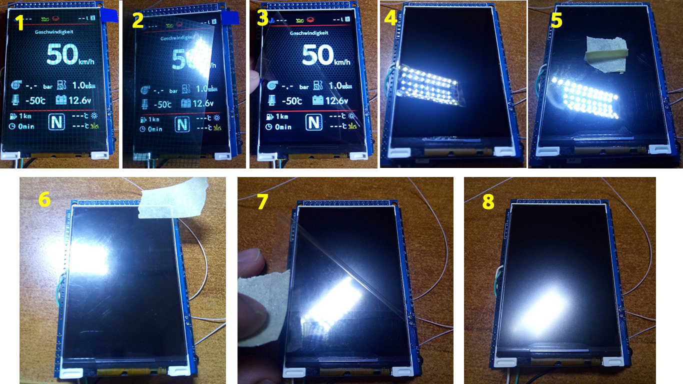
7. Next, you
need to glue the matte protective film so that the display does not
glare in the sun.
Unfortunately, the film may not always be included, but it is easy
to find on Marketplace, you can use a polyurethane matte screen
protector for any smartphone just cut out with scissors to the right
size.
7. Далее нужно приклеить матовую
защитную пленку, чтобы дисплей не бликовал на солнце. К
сожалению пленка не всегда может быть в
комплект, но ее легко найти на маркетплейсах, вы можете использовать
полиуретановую матовую защитную пленку для экрана любого смартфона
просто вырезав ножницами нужный размер.
Attention!
Be sure to stick the film!
Otherwise, you may damage the display!
Внимание!
Обязательно наклеить защитнкю матовую пленку
на дисплей!
В противном случае вы можете повредить дисплей!
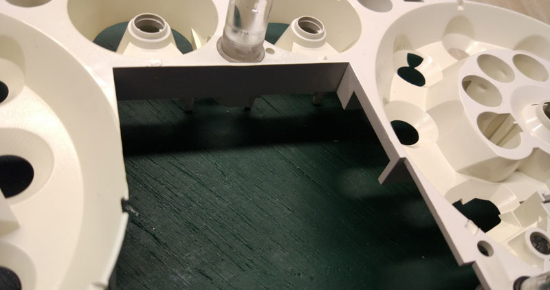
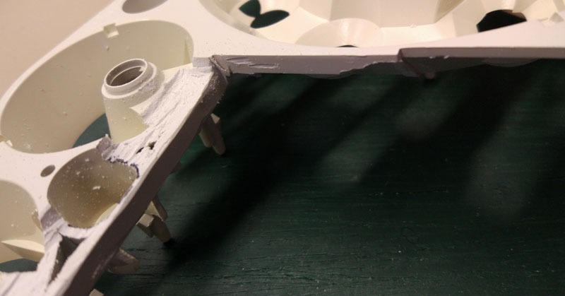
9.1.
Cut off the main beam guide part. On the red line. Leave the
semicircle.
9.1. Отрежьте пластик как
показано на фото
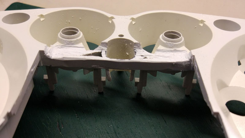
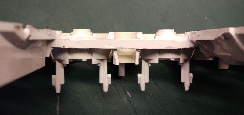
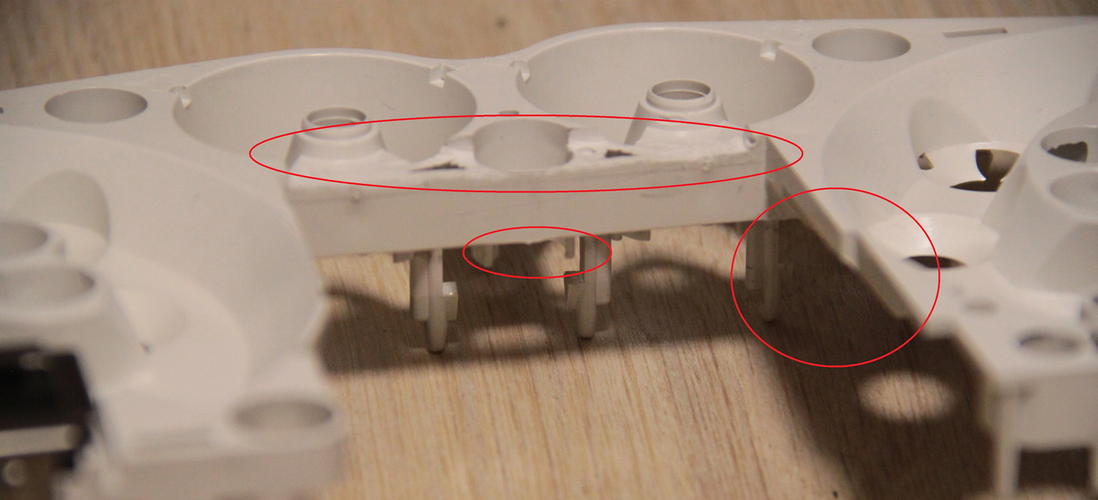
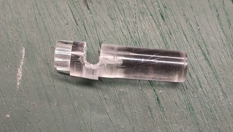
9.2.
Make a cut in the light guide.
9.2. Сделайте пропил в световоде.
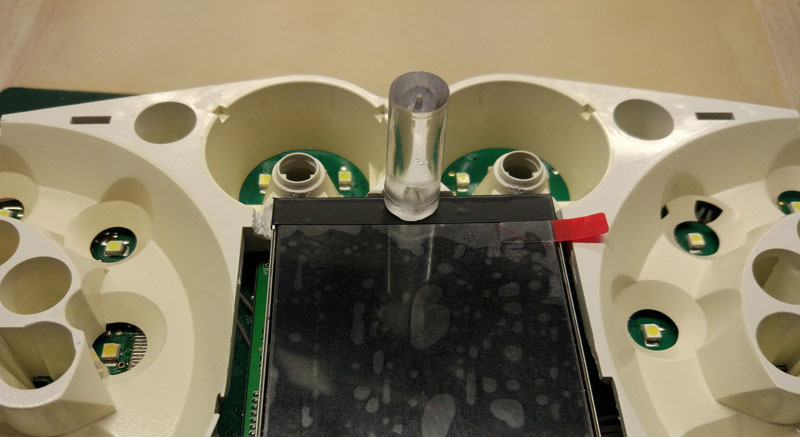
9.2. Install a white diffuser and cut off the excess (as shown in
the picture), then place the display and
align it so that it clearly fits into the cluster window.
9.2. Установите белый диффузор и отрежьте лишнее (как показано на
картинке), затем поместите дисплей и
выровняйте его так, чтобы он четко вписывался в окно
приборки.
9.2.1 Open the USB and solder what is marked
in red.
9
.2.1Откройте USB и припаяйте то, что отмечено
красным цветом.
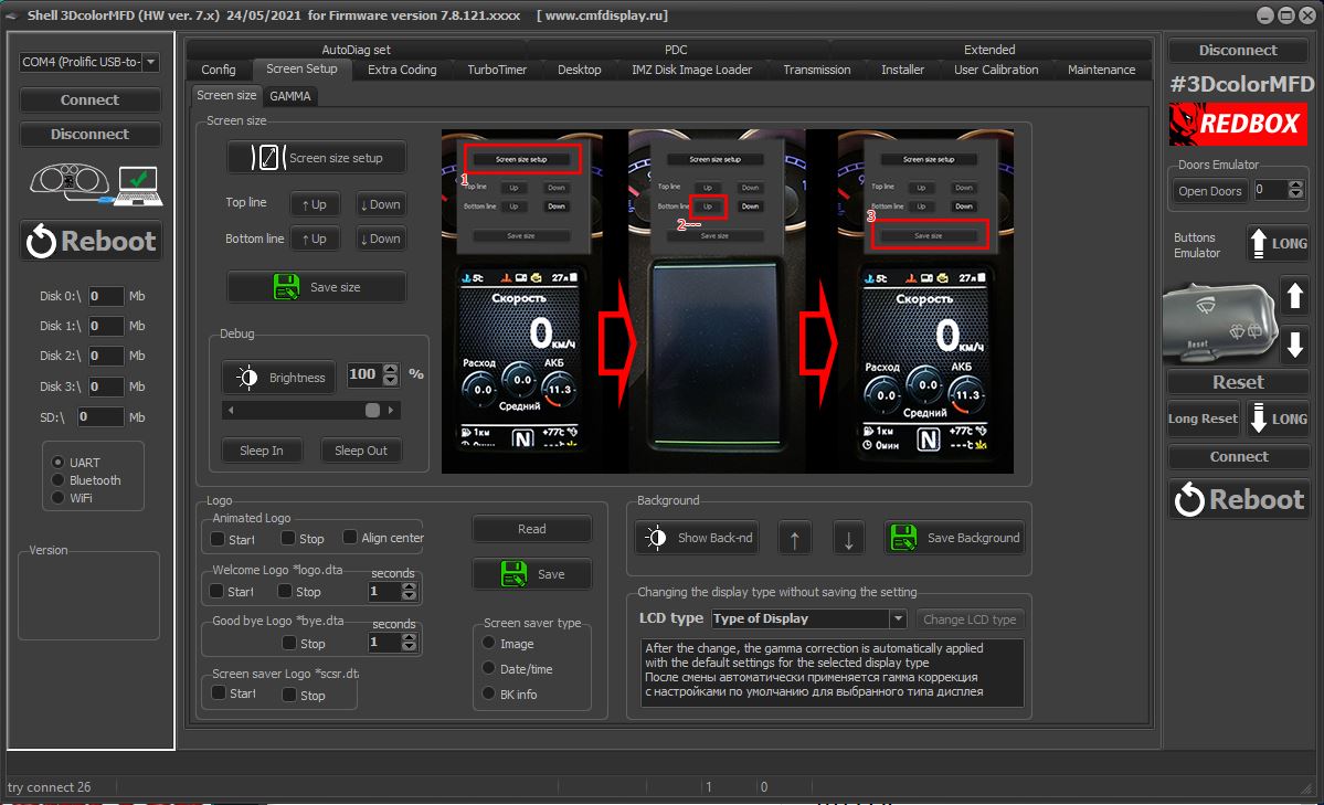
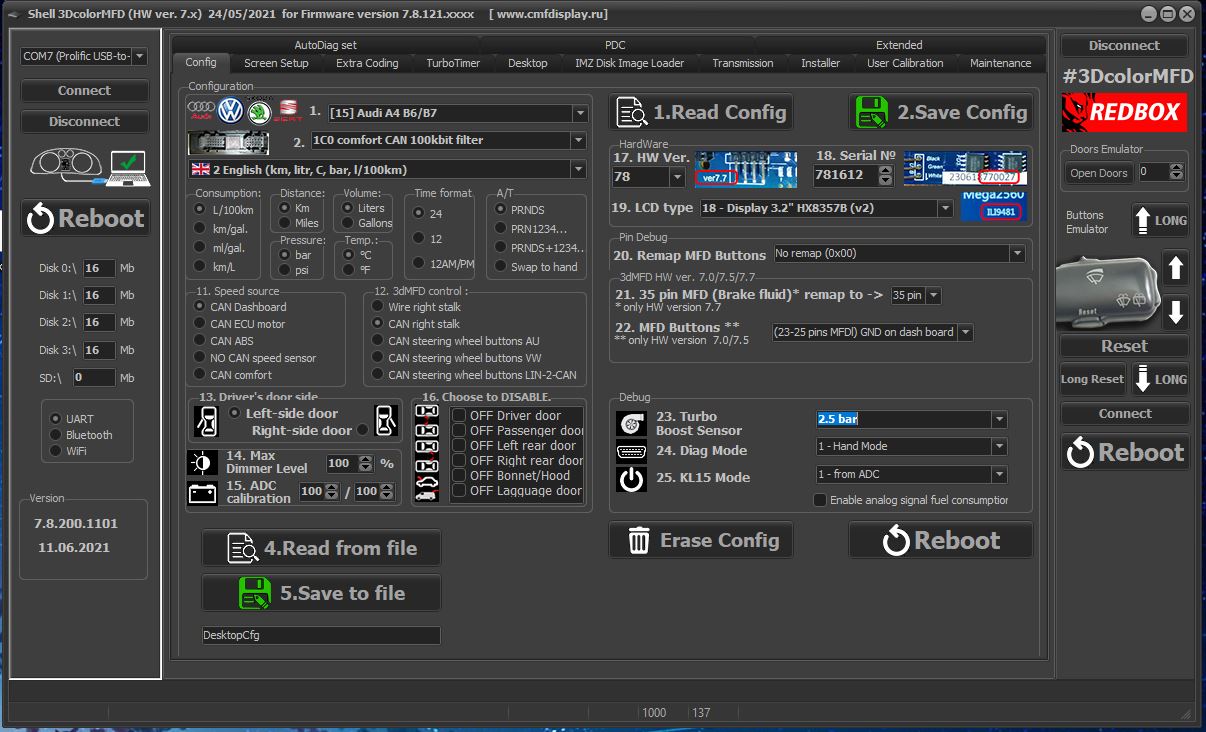
9.3.Using the Shell -> Screen Size program,
adjust the display frames according to the window in the tidy scale.
9
.3.
С помощью программы Shell -> Screen Size
настройте рамки дисплея по окну в шкале приборки.
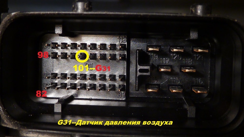
11.
Boost pressure control
11.
Подключить
отображение давления наддува
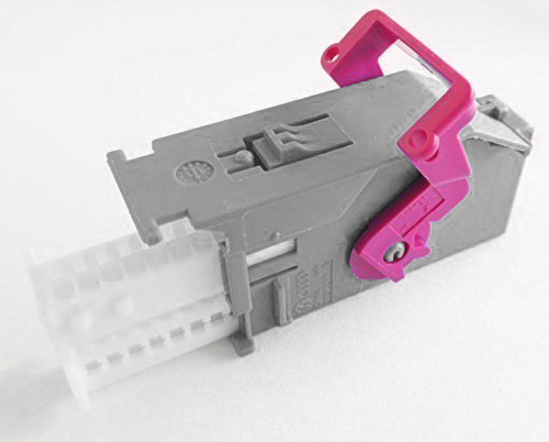
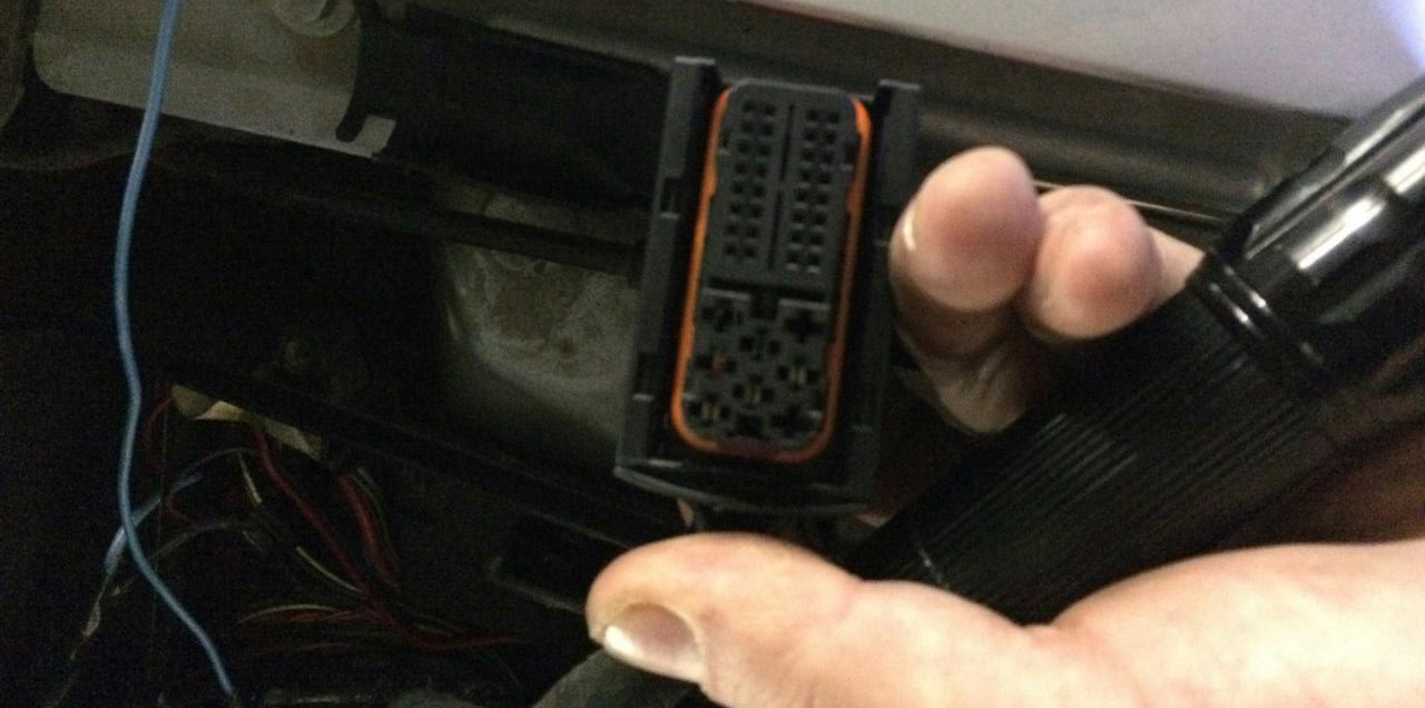
11.1. T
o connect the boost pressure control,
you will need to add one PIN to the dashboard32 pin
grey connector.The photo below is for example.
11.1. Чтобы подключить
отображение давления наддува, вам
нужно добавить провод от ЭБУд к
32пинсерого разъема. приборки. Фото ниже приведено для примера.
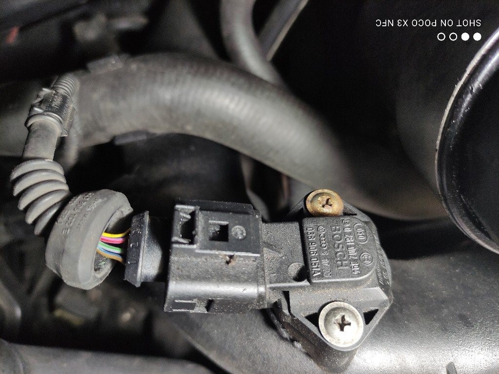
11.2. And the other end of the wire needs
to connect the signal wire of the boost sensor to the engine ECU.
In order to determine the desired wire, you need to measure the
voltage on this wire at idle, it should be 1.6V, (for a gasoline
engine) and 1.9V (for a diesel engine) with an increase RPM, the
voltage should increase.
If your motor is not in the table, find the boost sensor under the
hood, it has 4 wires, use a multimeter to determine the signal wire,
remember its color and find this wire in the ECU connector, or call
it with a multimeter.
11.2. А второй
конец провода нужно подключитьсигнальный
провод датчика наддува в ЭБУдвигателя.
Для того чтобы определить нужный провод, нужно измерить на
этом проводе на холостом ходу напряжение,
должно быть 1,6в,(для бензинового двигателя) и 1,9В
(для дизеля) с увеличением оборотов двигателя
напряжение должно увеличиваться.
Если вашего мотора нет в таблице, найдите под капотом датчик
наддува, у него 4 провода, с помощью
мультиметра определите сигнальный провод, запомните его цвет и
найдите этот провод в разъеме ЭБУд, или прозвоните с
помощью мультиметра.
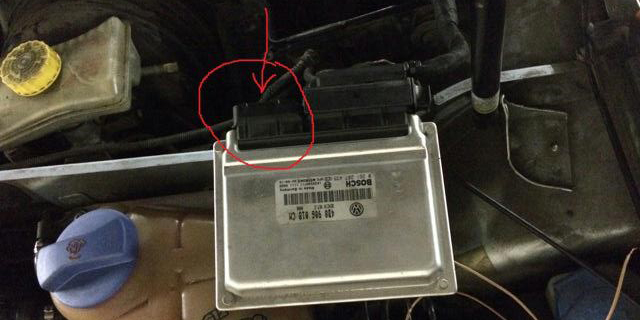
11.3.
Usually it isblue-graywire
(blue with a gray bar) to the incoming
on the 101st contact of a smaller brain connector.
(for a gasoline engine)
On
diesel engines (AVB and others): -71st
contact of themotor
brain,green-redWire
(green with a red stripe).
On
petrol (AWM and others): -101st
contact of themotor
brain,gray-bluewire
(gray with a blue stripe).
In
general, as far as I understand, at all B5-x diesel 1.9T
supercharging is connected to the 71st
and
the gasoline 1.8T is connected to the 101st contact.The
color of the wire can vary depending on the year / engine.
8.3.
Чаще
всего со стороны ЭБУД
к сине-серому проводу
(синий с серой полосой) приходящему
на 101-й контакт меньшего разъема мозга.
На дизелях (AVB и других):
— 71-й контакт моторного мозга, зелено-красный провод
(зеленый с красной полосой).
На бензиновых (AWM и других):
— 101-й контакт моторного мозга, серо-синийпровод
(серый с синей полосой).
Отличаться может цвет провода в зависимости от года/двигателя.
BES
2.7T
T121
101 pin
blue-gray
AJM
1.9TD
T121
71 pin
yellow-black
AKN
2.5TD
T121
71 pin
yellow-red
AUY
1.9TD
T121
71 pin
yellow-black
BQW
2.0TD
T94
78 pin
green-red
AWT
1.8T
T121
101 pin
blue-gray
AVG
1.9TD
T80
40 pin
yellow-green
AWM
1.8T
T121
101 pin
blue-gray
AFN
1.9TD
T121
70 pin
green-red
AWD
1.8T
T121
101 pin
blue-gray
AVB
1.9TD
T121
71 pin
green-red
AWP
1.8T
T121
101 pin
violet-gray
AVF
1.9TD
T121
71 pin
green-red
AUM
1.8T
T121
101 pin
violet-gray
AWX
1.9TD
T121
71 pin
green-red
AUQ
1.8T
T121
101 pin
violet-gray
AHF
1.9TD
T121
71 pin
yellow-black
ARZ
1.8T
T121
101 pin
violet-gray
ALH
1.9TD
T121
71 pin
yellow-black
ARX
1.8T
T121
101 pin
violet-gray
ARL
1.9TD
T121
71 pin
yellow-black
ANB
1.8T
T121
101 pin
blue-gray
ASV
1.9TD
T121
71 pin
yellow-black
APU
1.8T
T121
101 pin
blue-gray
ASZ
1.9TD
T121
71 pin
yellow-black
APB
1.8T
T121
101 pin
blue-gray
ATD
1.9TD
T121
71 pin
yellow-black
AMB
1.8T
T121
101 pin
blue-gray
AXR
1.9TD
T121
71 pin
yellow-black
11. 11. After you have laid the
signal wire from the engine ECU to the cluster,
make a setting in the Shell program so that 3dMFD displays the turbo
boost pressure. You need to set the type
of your boost sensor, you can do this experimentally by selecting it
from the list in the Shell program.
11.
После того как вы проложили сигнальный провод от ECU
двигателя к приборке
сделайте настройку в
программе Shell, для того чтобы 3dMFD
отображал давление наддува турбины.
Вы должны установить тип вашего датчика давления, вы можете сделать
это опытным путем подбирая его по списку в Шелл программе.
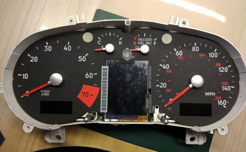
12. Assembly.
And then we collecteverythingin
the reverse order withoutforgetting
to calibrate the
needleswith the help of the WAG-com.
12.
СБОРКА.
Собирайте все в обратном порядке, не забывая калибровать иглы с
помощью программы VAG-com.
12.1.
To
do this, connect the device to the machine without installing the
glass, connect the VAG-com.
12.1 Для этого
установите приборку в автомобиль
(без стекла) и подключите его VAG-com.
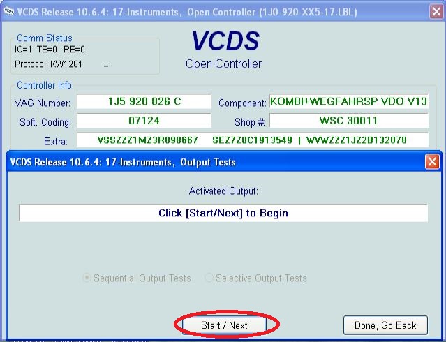
12.2.Go
into the 17-unit dash panel
12.2Зайти
в 17-блок панель приборов
12.3.Select
test performers.
12.3.Выбрать
"Тест исполнителей".
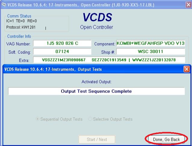
12.4.Choosing
in turn a tachometer, temperature and the rest, the arrows in turn
will be
Do a turn on
the whole scale, and then freeze on:
12.4 Сделайте тест стрелок.
Выборайте по очереди: тахометр, температура охлаждающей
жидкости, уровень топлива и скорость Стрелки
пройдут по вей шкале, а затем
остановятся
в контрольных точках. Запомните или сделайте фотографию разницы в
показания. Нажмите
«Готово» и выйдите из блока. Выключите зажигание, выньте
ключ и установите иглы в правильное положение, повернув их
назад против часовой стрелки.
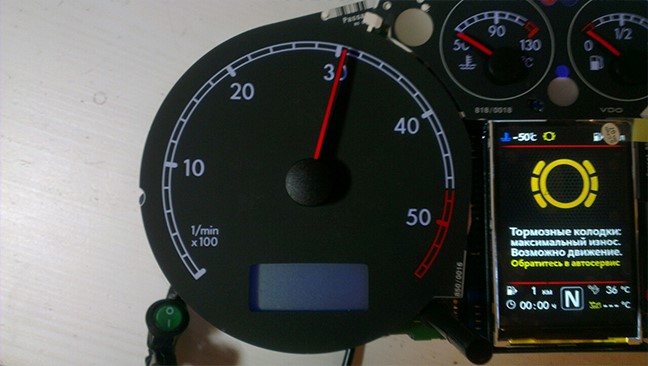
12.5.Tachometer - 3
thousand revolutions
12.5.Тахометр - на 3 тыс. оборотов
12.6.Pace.Coolant
- middle
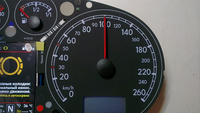
12.6.
Спидометр - на 100
км/ч
12.7. Fuel
level - middle
12.7. Уровень температуры ОЖ -
по средине
12.8.Speedometer
- at 100 km / h
12.8. Уровень топлива -
по средине
Then check everything
again
You can not turn the needles too quickly correcting the position,
you can damage the motors of the needles
You can not turn the needles, when there is power on the device.
13. Put back the cluster glass and put the cluster back into the
car.
14.Take a photo and post it on all social networks.
Go to auto club meeting and brag to your friends.
15. Show it to your girlfriend/wife with words: «Look what a cool
thing I bought for just 20 bucks! » =)
Затем проверьте все снова
Вы не можете поворачивать стрелки слишком быстро, исправляя
положение, вы можете повредить двигатели стрелки, а
так же нельзя поворачивать стрелки при включенной приборке.
13. Поставьте обратно стекло кластера и
вставьте кластер обратно в автомобиль.
14. Сфотографируйте и разместите его во всех
социальных сетях.Отправляйтесь
на встречу автоклуба и хвастайся друзьям.
15. Покажите это своей девушке / жене со
словами: "Посмотри, какую классную вещь я купил всего за 20 баксов!"
:)))
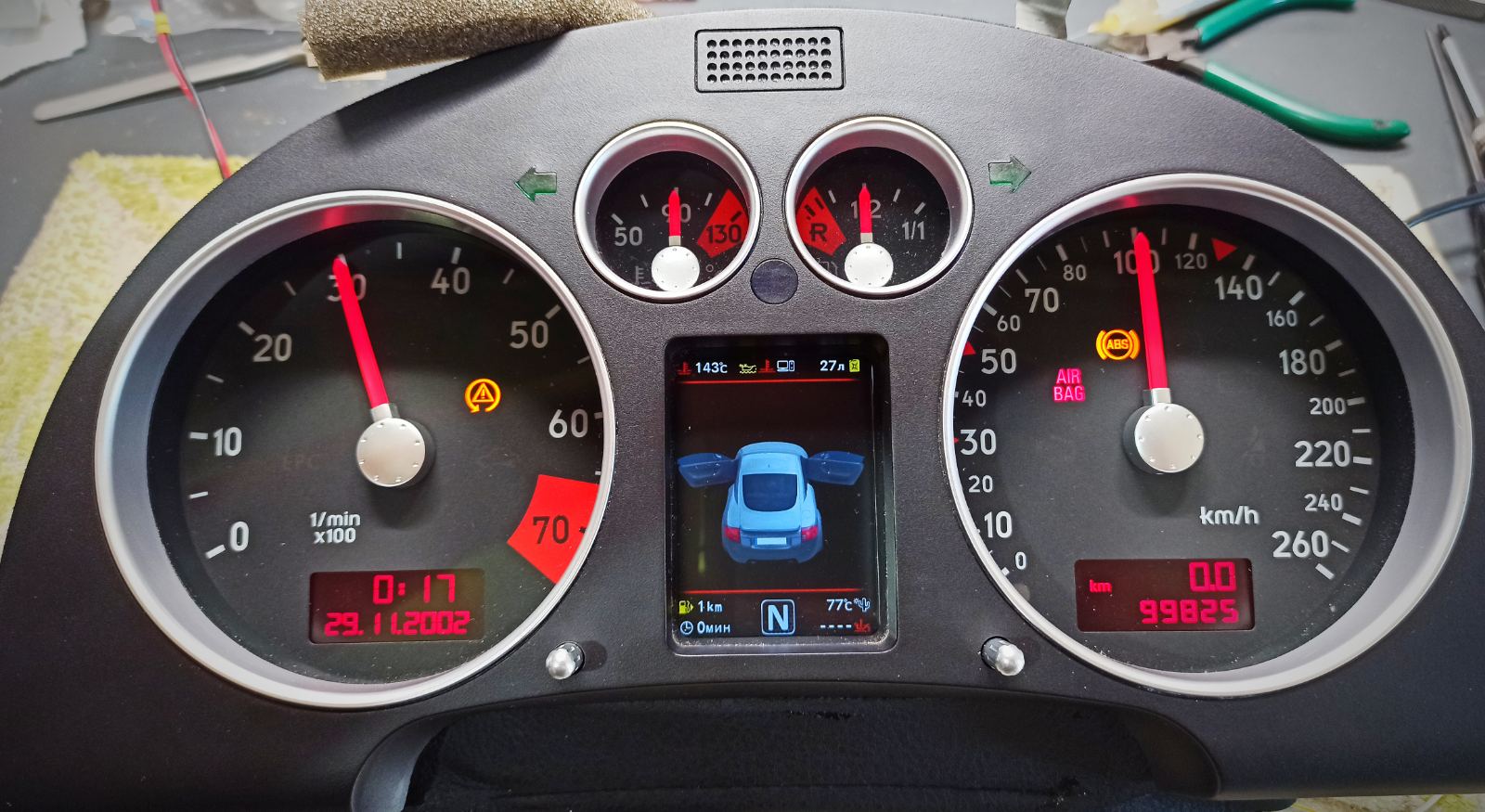
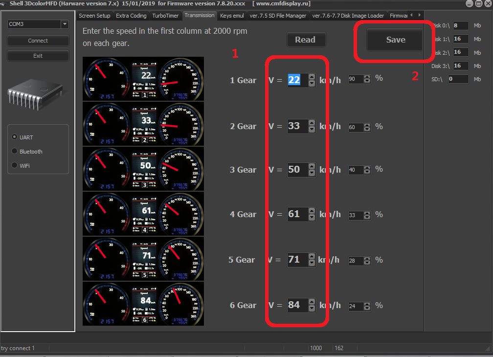
In cars with manual gearbox,
the ECU has no information about which gear you have selected, and
3dMFD cannot read it,
so 3dMFD shows the selected gear in terms of the ratio of driving
speed to RPM.
To calibrate, you must enter the travel speed in each gear at 2000
RPM in the first column.
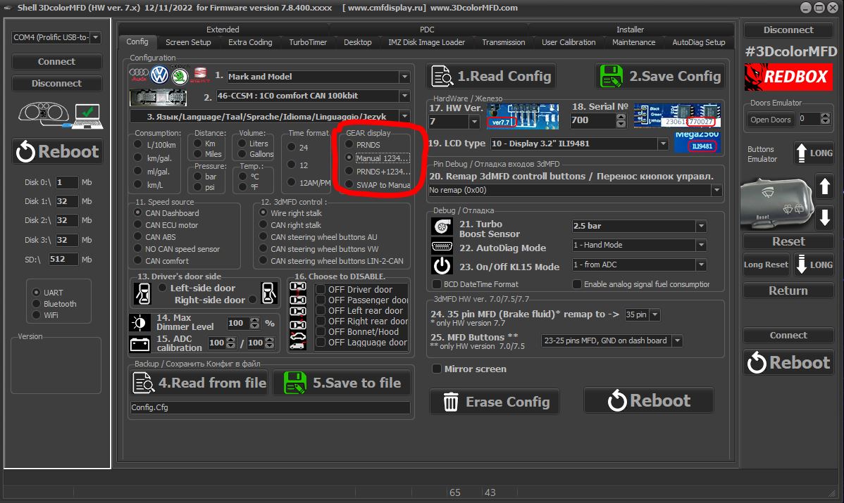
Also, 3dmfd does not mean that neutral gear is engaged.
Only when you press the clutch pedal does the N signal appear.
В автомобилях с механической коробкой передач ЭБУ
двигателя не имеет информации о том, какую передачу вы
выбрали,
и 3dMFD не может ее прочитать, поэтому 3dMFD показывает выбранную
передачу по соотношению скорости движения и оборотов
двигателя в минуту.
Для калибровки необходимо ввести в первую колонку скорость движения
на каждой передаче при 2000 об/мин.
Кроме того, 3dmfd не означает, что включена нейтральная передача.
Только при нажатии на педаль сцепления появляется сигнал N.
If the N signal does not appear when the clutch pedal is depressed.
Check the settings in the Config tab
Если при нажатии на педаль сцепления не появляется сигнал N.
проверте настройки во вкладке Конфиг
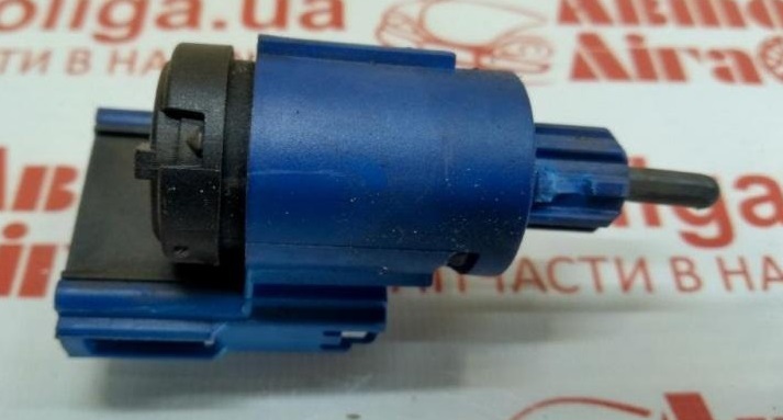
If the settings in the Configure tab are correct, but the N signal
does not appear when the clutch pedal is depressed.
Check if the clutch pedal micro switch is present and working.
Если настройкf во вкладке Конфиг правильная, но при нажатии на
педаль сцепления не появляется сигнал N.
Проверте наличие и работоспособность микровыключателся педали
сцепления.


.jpg)