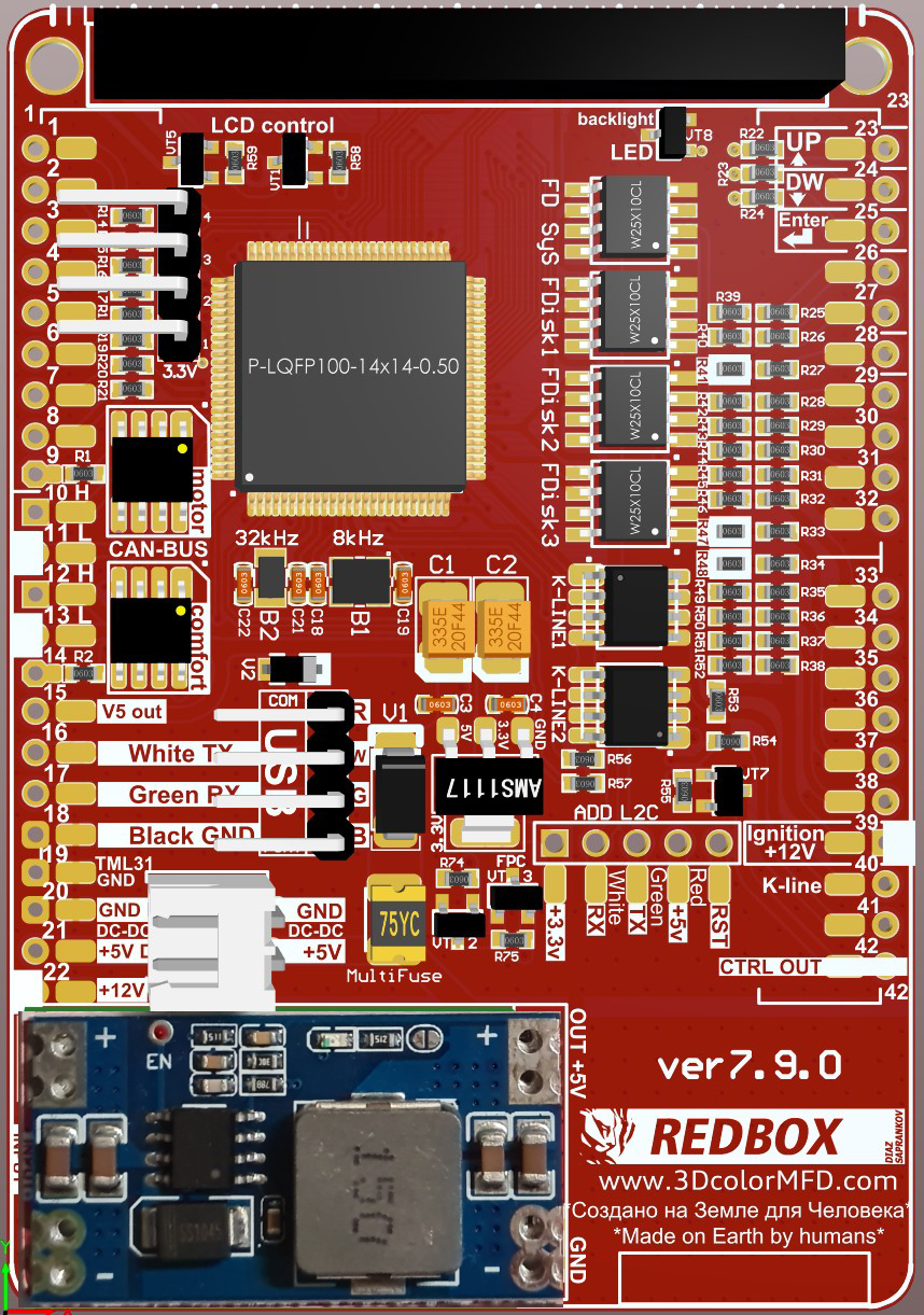
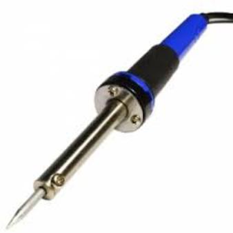
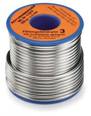
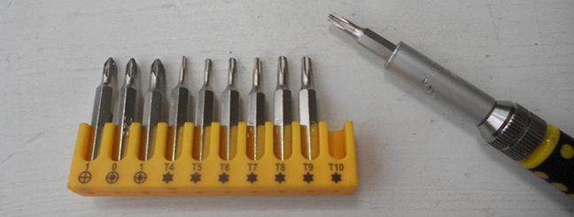
You will need:
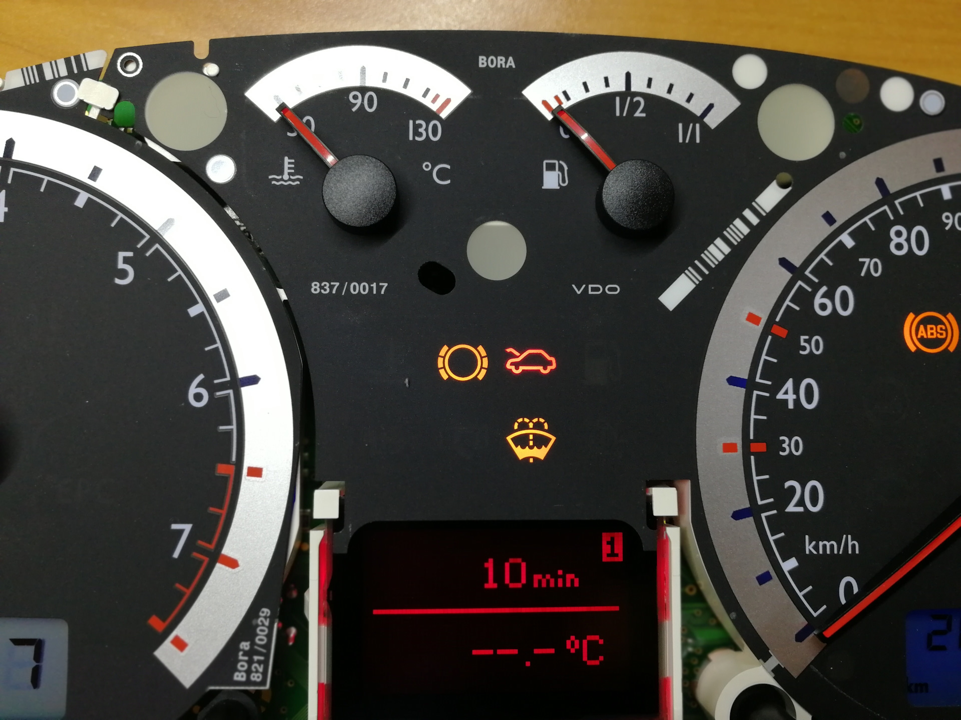
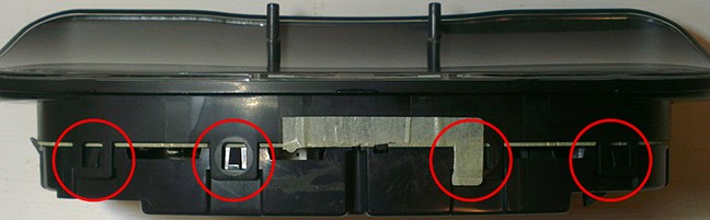
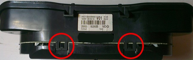
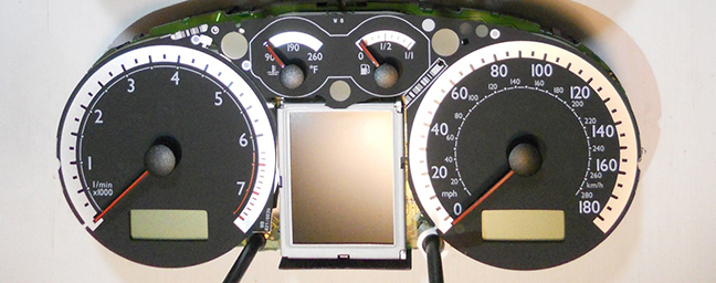
Bend all the latches and neatly remove the front of the case (with glass).
|
|||||||||||||||||||||||||||||||||||||||||||||||||||||||||||||||||||||||||||||||||||||||||||||||||||||||||||||||||||||||||||||||||||||||||||||||||||||||||||||||||||||||||||||||||||||||||||||||||||||||||||||||||||||||||||||||||||||||||||||||||||||||||||||||||||||||||||||||||||||||||||||||||||||||||||||||||||||||||||||||||||||||||||||||||||||||||||||||||||||||||||||||||||||||||||||||||||||||||||||||||||||||||||||||||||||||||||||||||||||||||||||||||||||||||||||||||||||||||||||||||||||||||||||||||||||||||||||||||||||||||||||||||||||||||||||||||||||||||||||||||||||||||||||||||||||||||||||||||||||||||||||||||||||||||||||||||||||||||||||||||||||||||||||||||||||||||||||||||||||||||||||||||||||||||||||||||||||||||||||||||||||||||||||||||||||||||||||||||||||||||||||||||||||||||||||||||||||||||||||||||||||||||||||||||||||||||||||||||||||||||||||||||||||||||||||||||||||||||||||||||||||||||||||||||




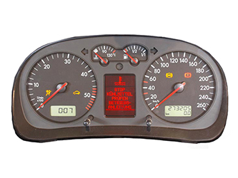
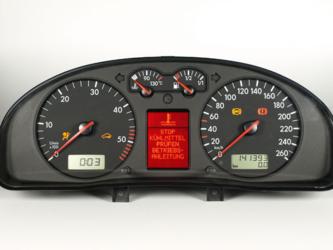
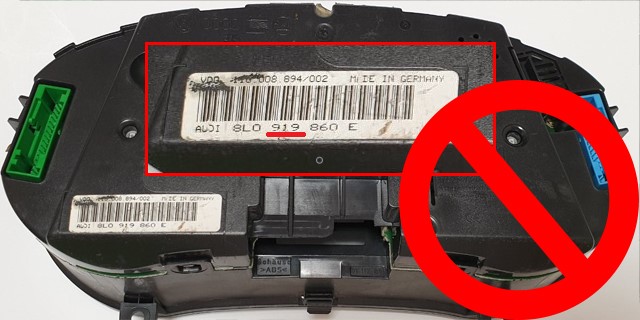
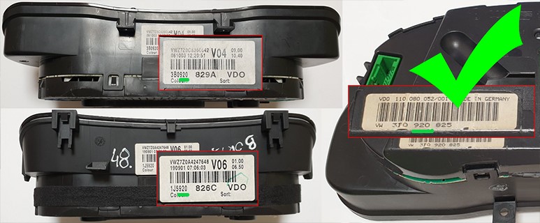
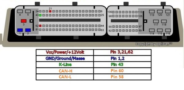
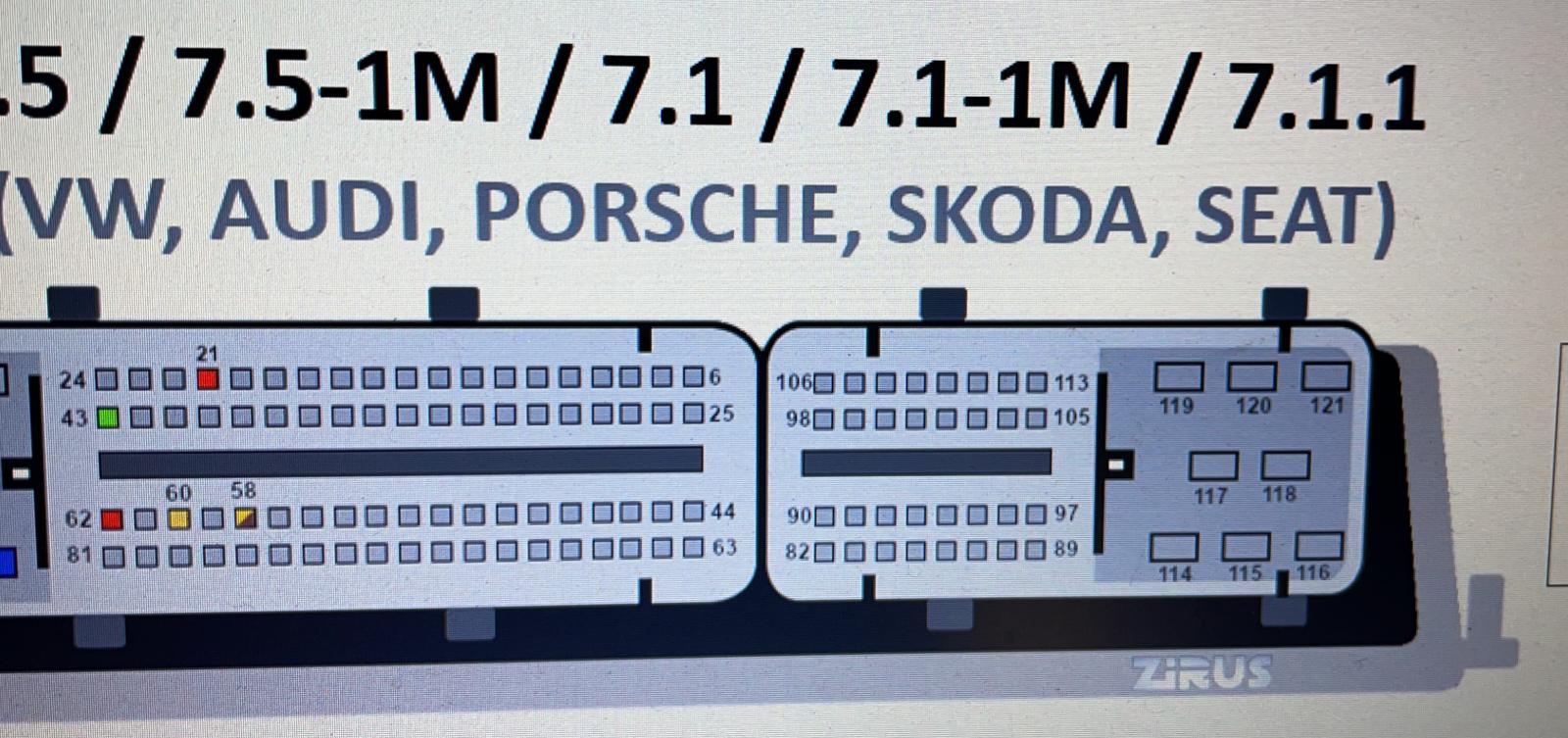
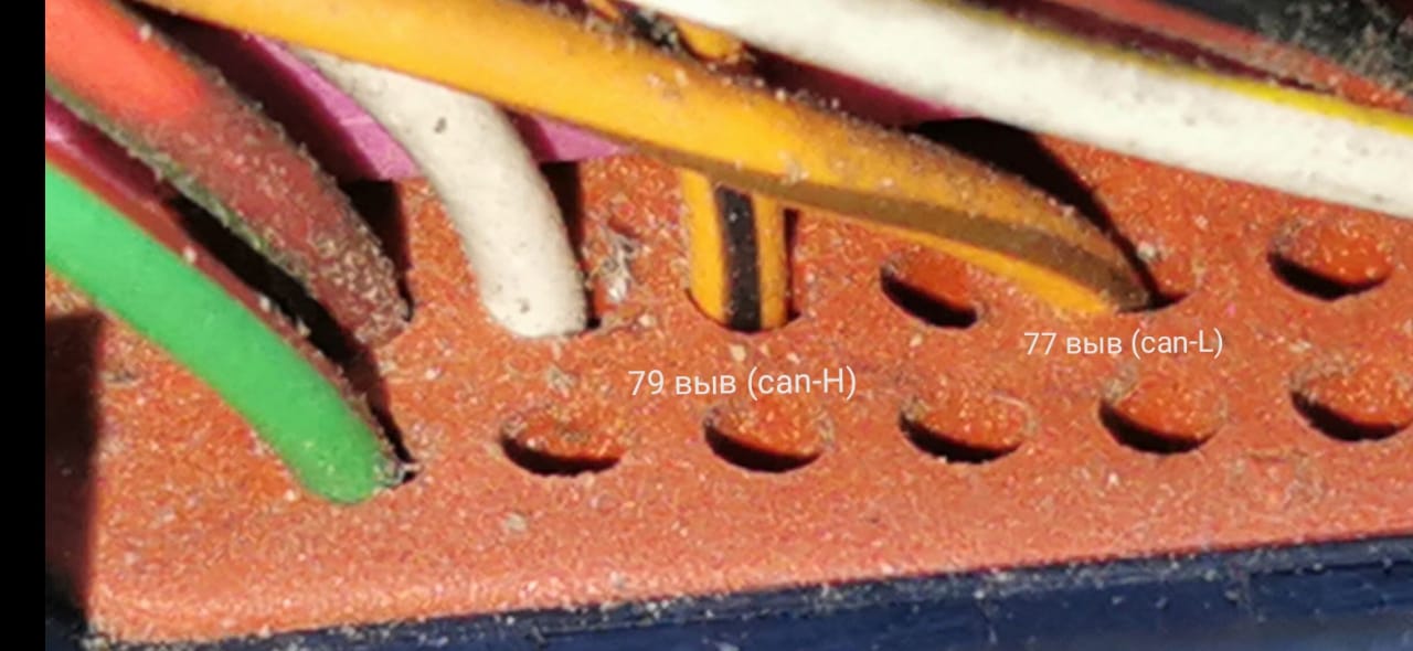

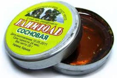
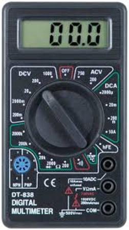
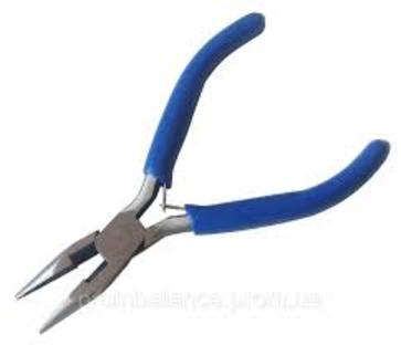
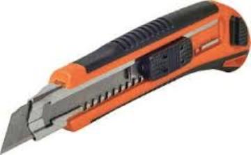
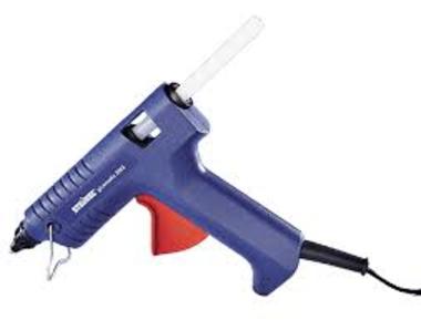
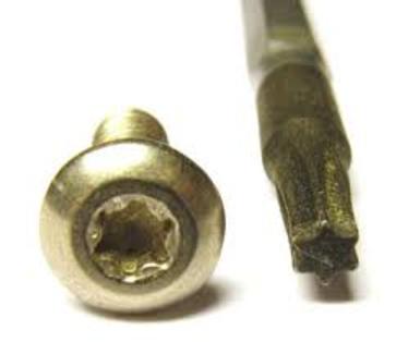
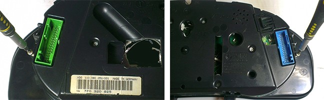
|
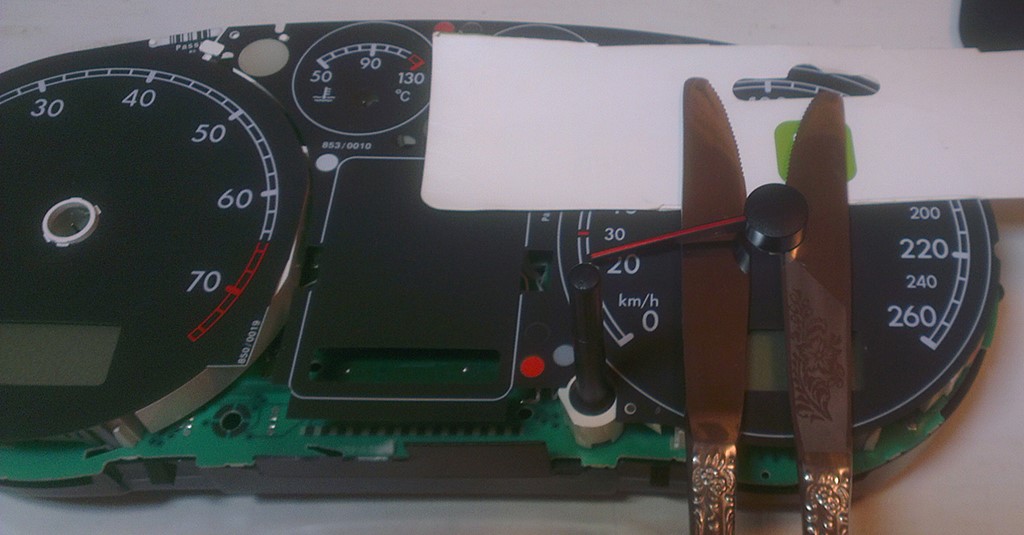
1.2 Remove the needles.
|
 |
|
|
1.2 Удалите
стрелки.
|
|
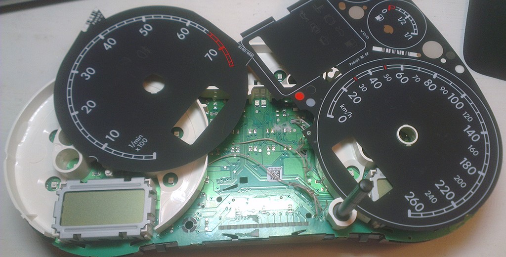
1.3. Then
remove the substrate. |
1.4.
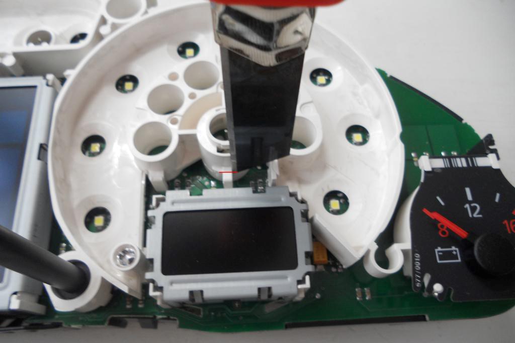
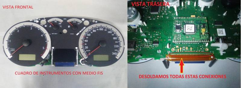
Remove the small displays under the speedometer and tachometer and
white plastic.Cut
the jumpers, we work carefully, so as not to damage the board. Удалите маленькие дисплеи и белый пластик рассеивателя. |
|
|
 |
|
|
   |
|
|
1.5.
Remove
white plastic (noFIS) Удалите белый пластик |
|
|
|
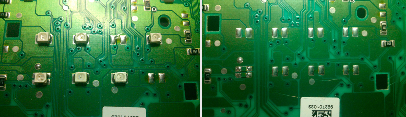
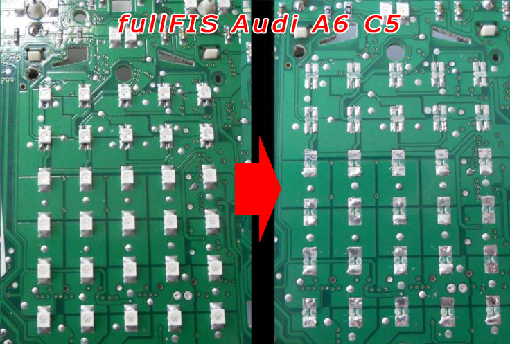
1.6. Then you need to remove all the LEDs that are were under the standard display
1.6.
Затем нужно убрать все светодиоды, которые были
|
||
 |
||
|
|
 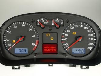 |
||
|
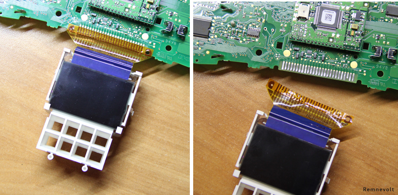
1.5. Remove display (halfFIS)
It is necessary to remove the display by gently
heating the loop with which it is soldered to the board,
Снимать дисплей необходимо, аккуратно нагревая
шлейф, которым он припаян к плате, |
|
||
 |
|||
|
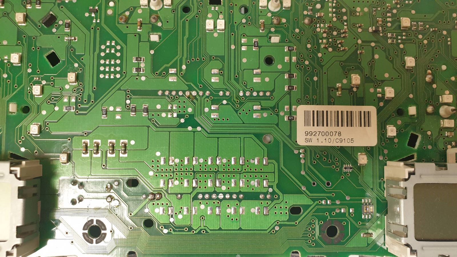
1.6. Remove all the LEDs that are were under the standard display
1.6.
Удалите все светодиоды, которые были под
штатным дисплеем. |
|||
 |
|||
|
1. 7. Remove all metal pins
1.7.
Удалите металлические пины |
|||
|
|||
 |
|
|
|
1.5. Remove display (fullfFIS)
It is necessary to remove the display by gently
heating the loop with which it is soldered to the board,
Снимать дисплей необходимо, аккуратно нагревая
шлейф, которым он припаян к плате,
|
|
|
|
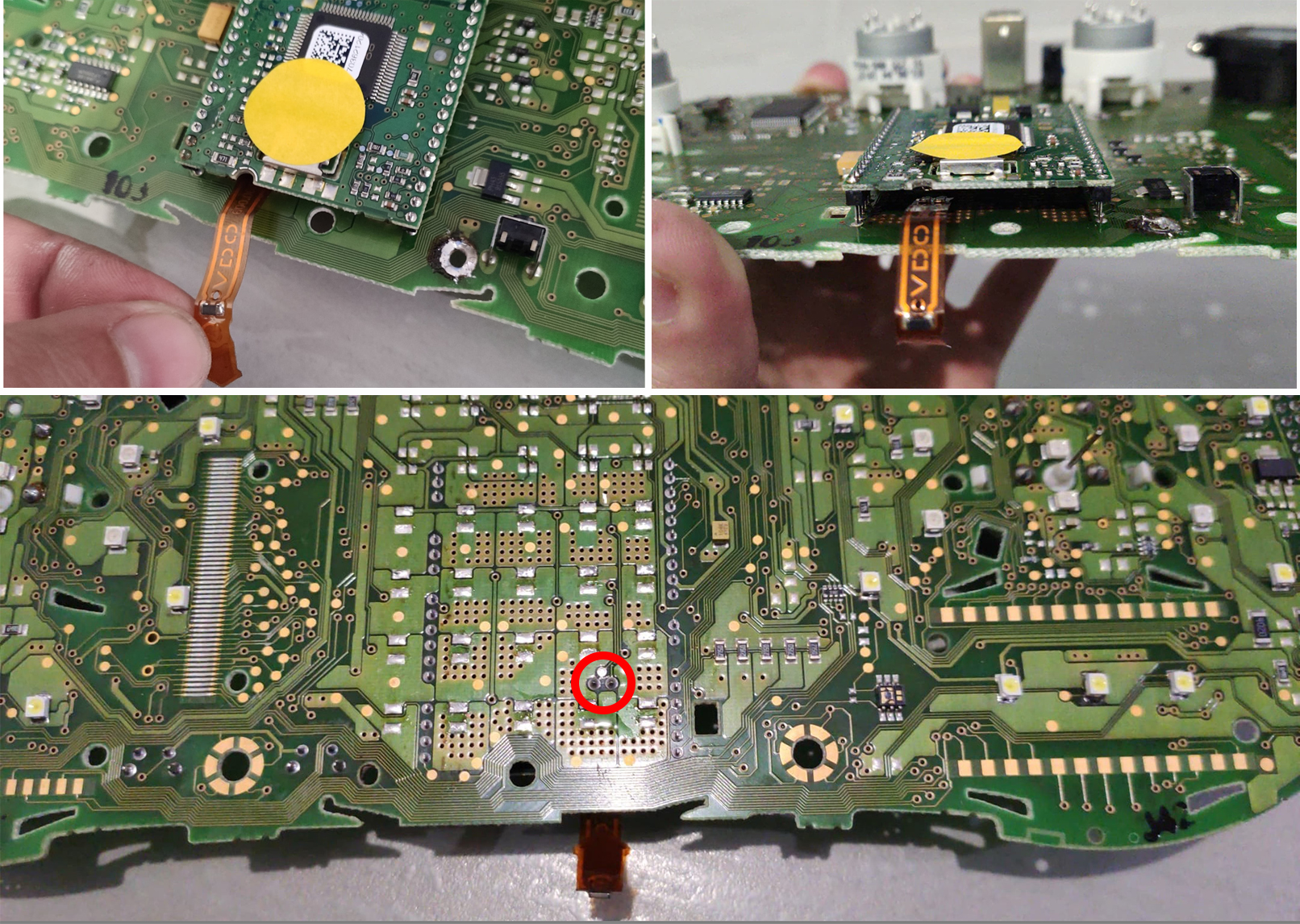
1.5.1. Remove temperature sensor. There is a temperature sensor in a fullFIS clusters. It can be removed with a soldering iron or simply cut off the sensor tape in any convenient place, so that it does not interfere later.
1.5.1. Удалите датчик температуры.
|
 |
|
|
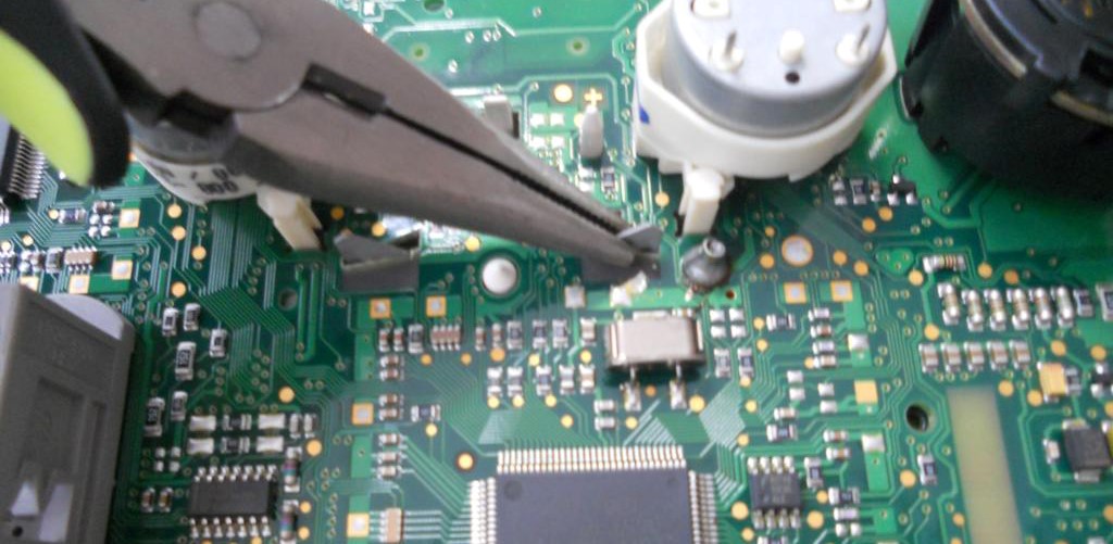
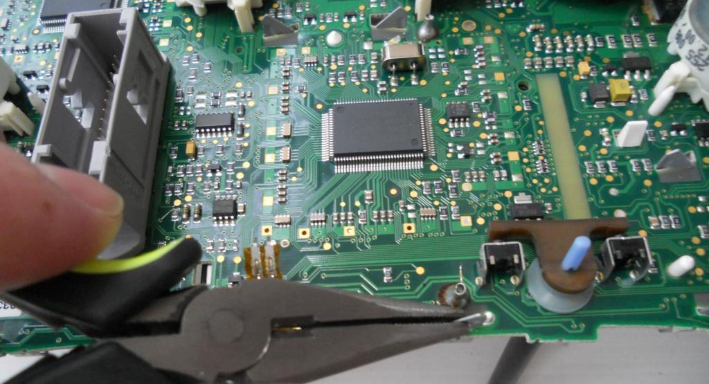
1.5.2. With
the help of pliers, we bend
the metal clamps restraining fullFIS
display. 1.5.2. С помощью плоскогубцев отгибаем металлические зажимы, удерживающие оригинальный дисплей. |
||
  |
||
|
1.5.3. Remove the white display holder.
1.5.3. Снимаем белый
держатель дисплея.
|
|
|
|
1.6. Then you need to remove all the LEDs that are were under the standard display
1.6.
Затем нужно убрать все светодиоды, которые были
|
|
|
|
1.7. Remove all metal pins 1.7. Удалите металлические пины
|
|
|
|
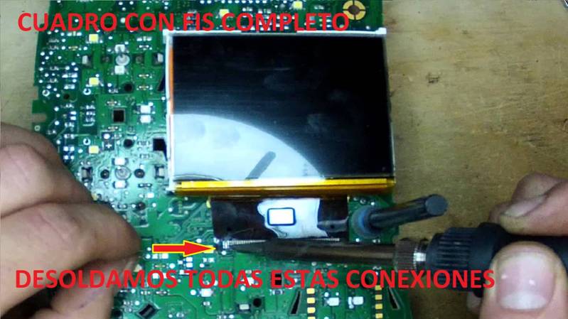
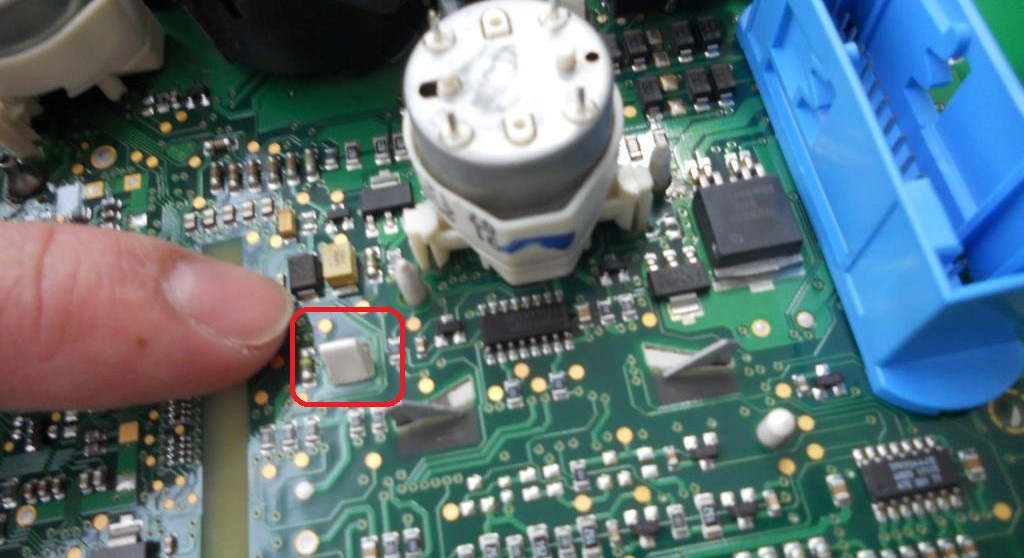
1.8. We make sure
that there are no jumpers made of tin. 1.8. Следим за тем,
чтобы не было перемычек из олова и. |
|
|
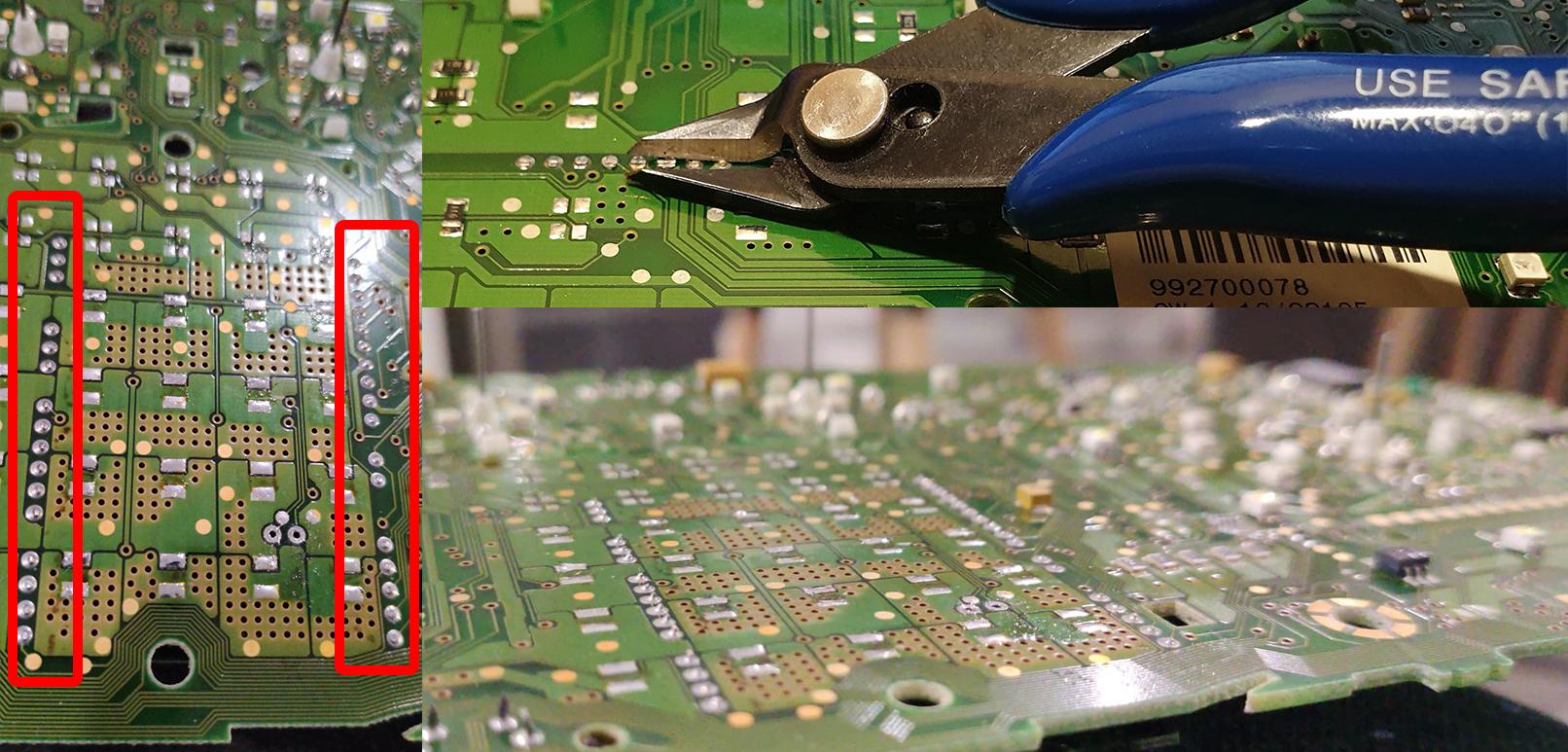
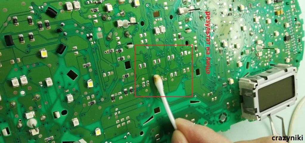
|
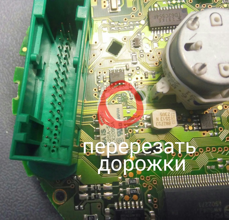
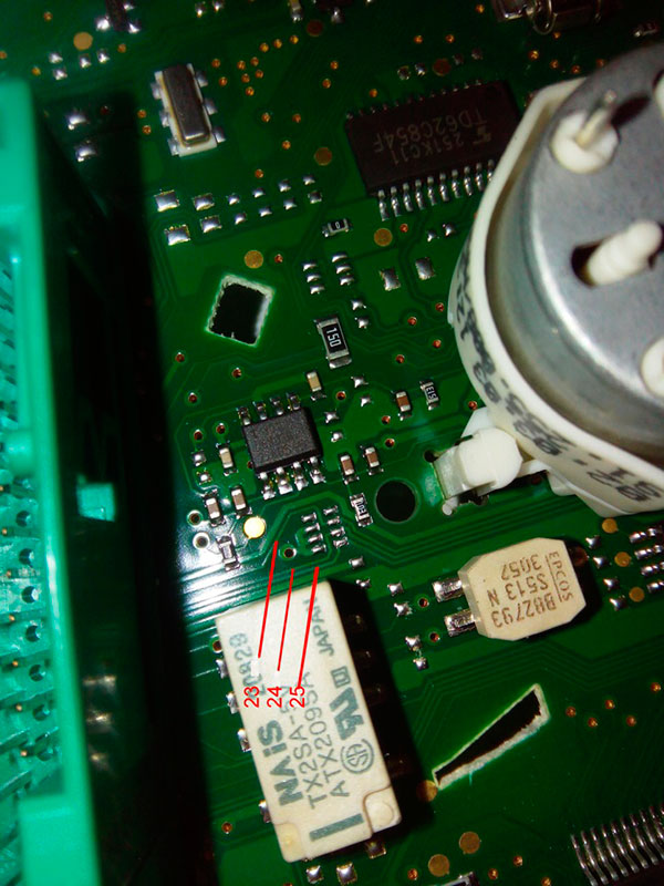
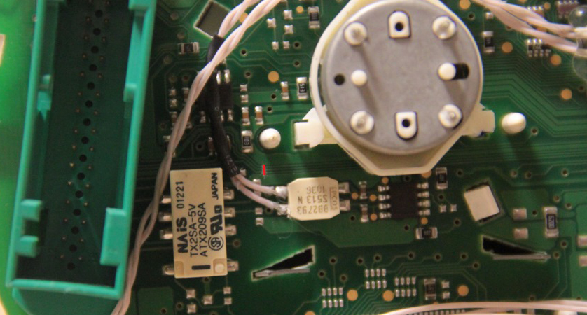
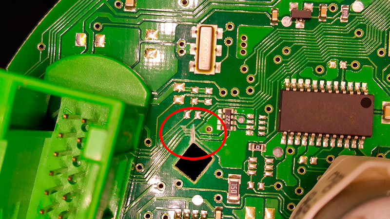
1.9.
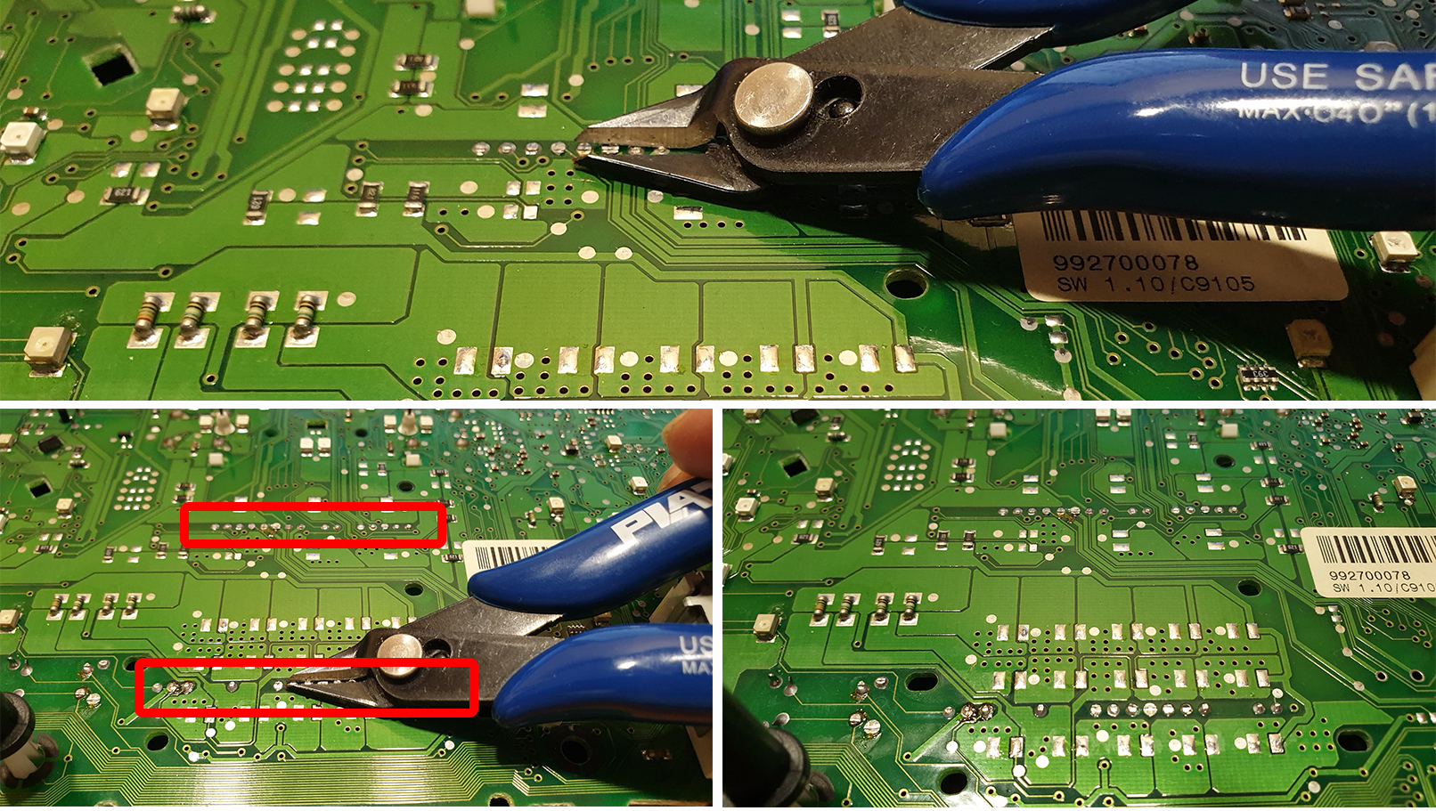
VERY IMPORTANT:
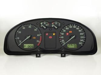
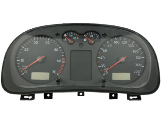
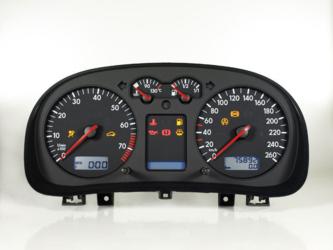
Below you can see photos of some clusters.
|
1.9. ОЧЕНЬ
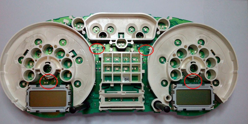
ВАЖНО: Для приборок с установленным HalfFIS или fullFIS необходимо найти и перерезать дорожки от контактов 23,24,25 зеленого разъема приборки. После этого убедитесь, что на контактах 23, 24, 25 контактов 0 вольт. Ниже вы можете увидеть фотографии некоторых кластеров. На вашем устройстве треки могут быть расположены в другом месте. Для кластеров noFIS вам просто нужно проверить, чтобы на выводах 23, 24, 25 было 0 вольт. |
|
|
|
1.10.
IMMO 2
1.10.
ИММО 2
|
 |
||
|
|
|||
|
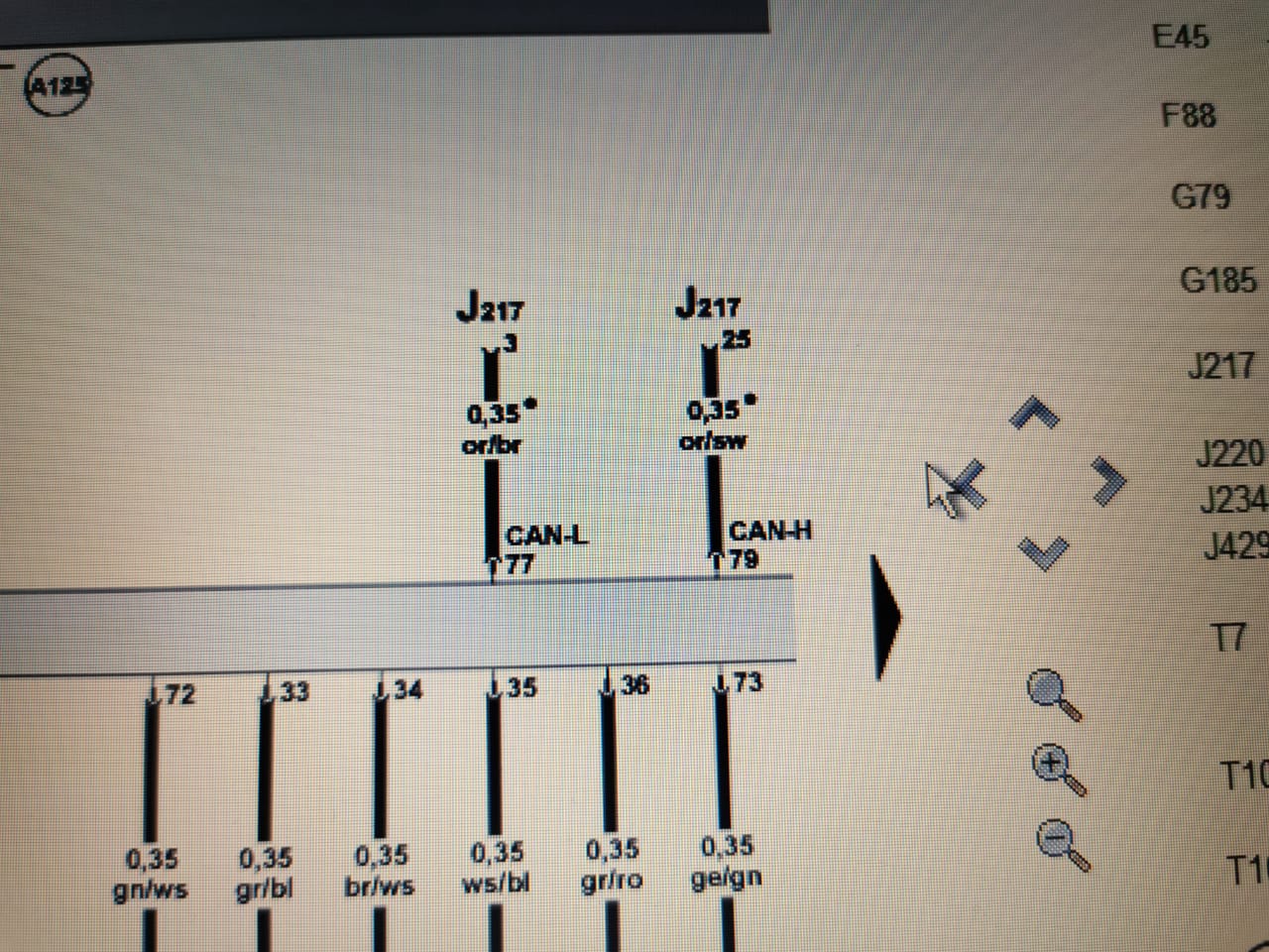
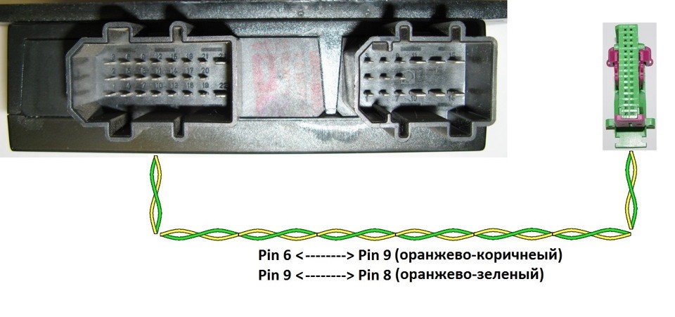
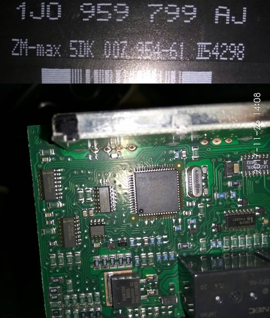
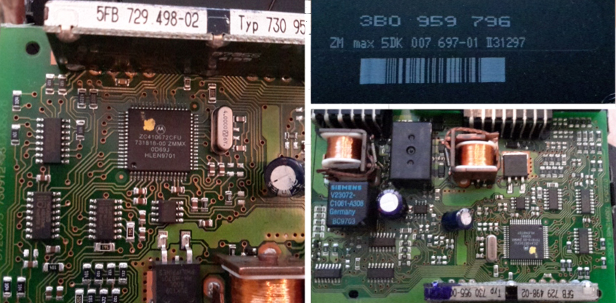
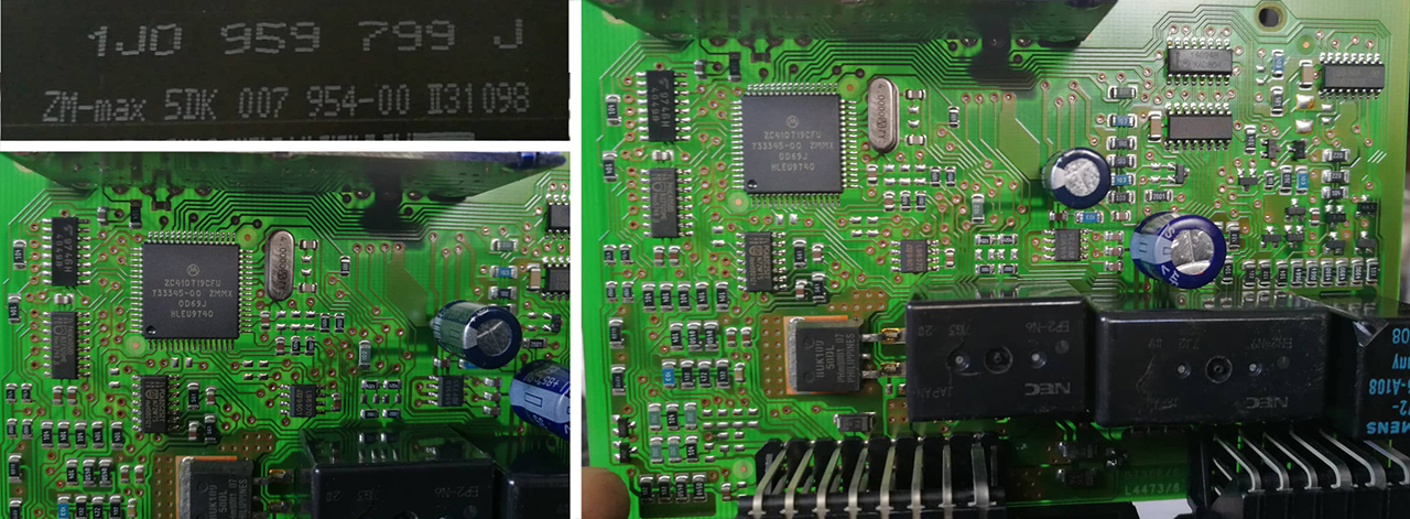
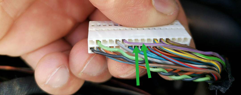
1.10.1. If these CAN-bus wires are NOT connected to the comfort unit you need to disassemble the comfort block and make sure that there is a CAN-bus chip 1.10.1. Если эти провода CAN-шины НЕ подключены к блоку комфорта, вам необходимо разобрать блок комфорта и убедиться в наличии микросхемы CAN-шины.
|
|||
 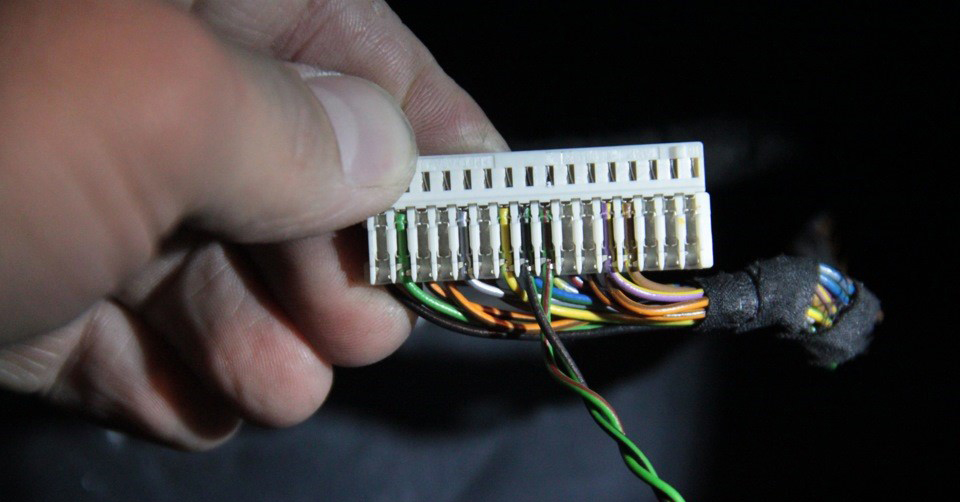 |
|
1.11. IMMO3 Cluster Installation in a
vehicle with IMMO2
1.11.
Установка кластера IMMO3 в автомобиле с IMMO2 |
|
|
|
|
|
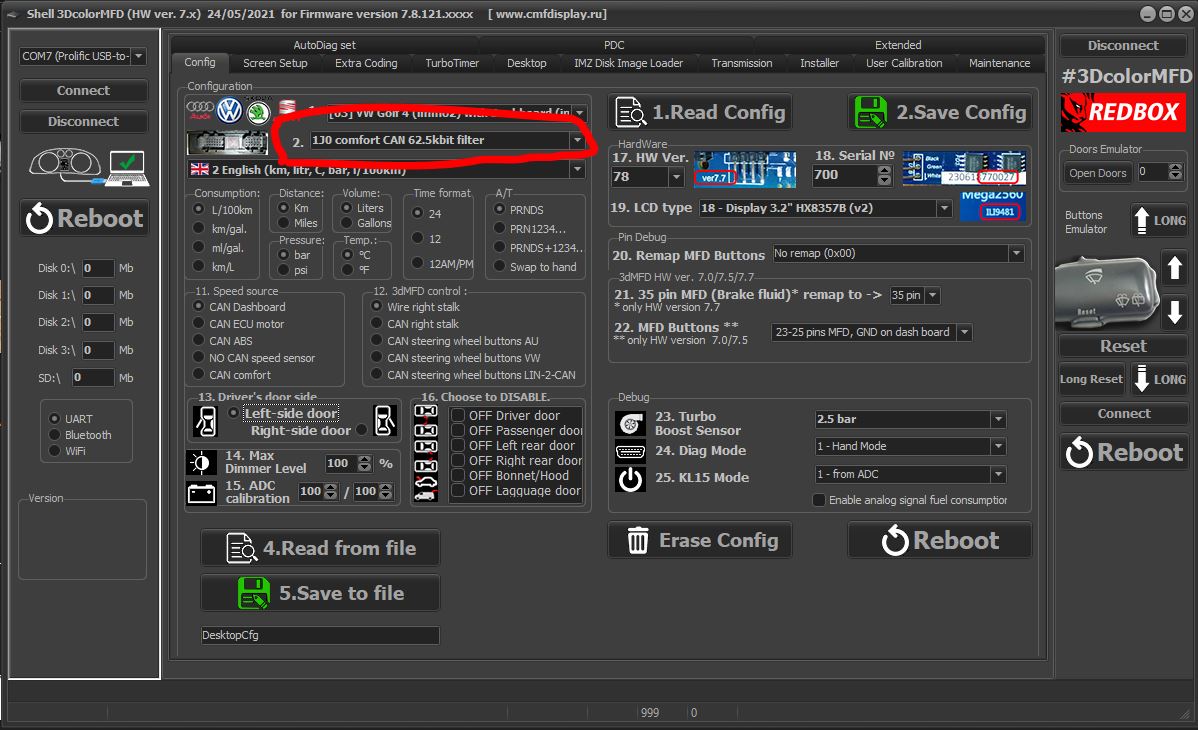
1.12. then make a setting in the
Shell program so that 3dMFD
working with "1J0 comfort CAN 62.5kbit filter" 1.12. и затем сделать настройку в программе Shell, для того чтобы 3dMFD работал с "1J0 comfort CAN 62.5kbit filter" |
|
1.13. If you are Installating IMMO3 cluster in a vehicle with IMMO2,
you should activate the ambient temperature sensor in the cluster`s
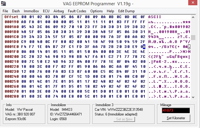
EEprom. 1 .13. Если вы устанавливаете приборку IMMO 3 в автомобиль с IMMO2, необходимо активировать датчик температуры окружающей среды в EEprom кластера.
https://www.drive2.ru/l/9288217/
|
|
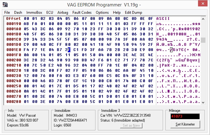
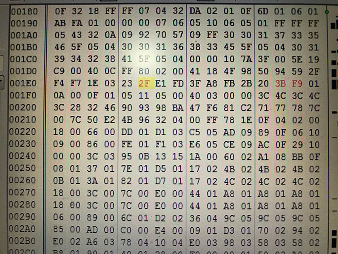
Passat B5 You need to change 1ef from 08 to 01 line 0001E0 column F
|
Golf 4 Cluster 1J0920806G no fis no show temp in dispay You need to change 1e5 from 2B to 2F line 0001E0 column 5
|
|
Change 2B in 2F and work
I changed that one 1E0 column 6 from 2B to 2F and it works
|
|
|
|
|
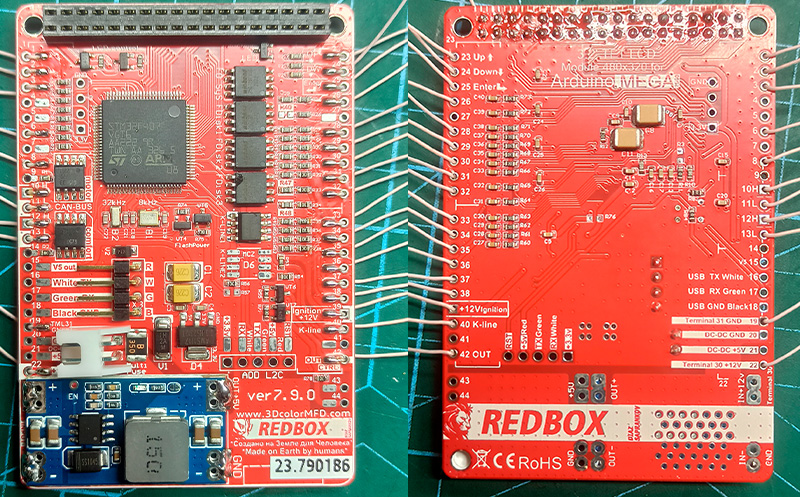
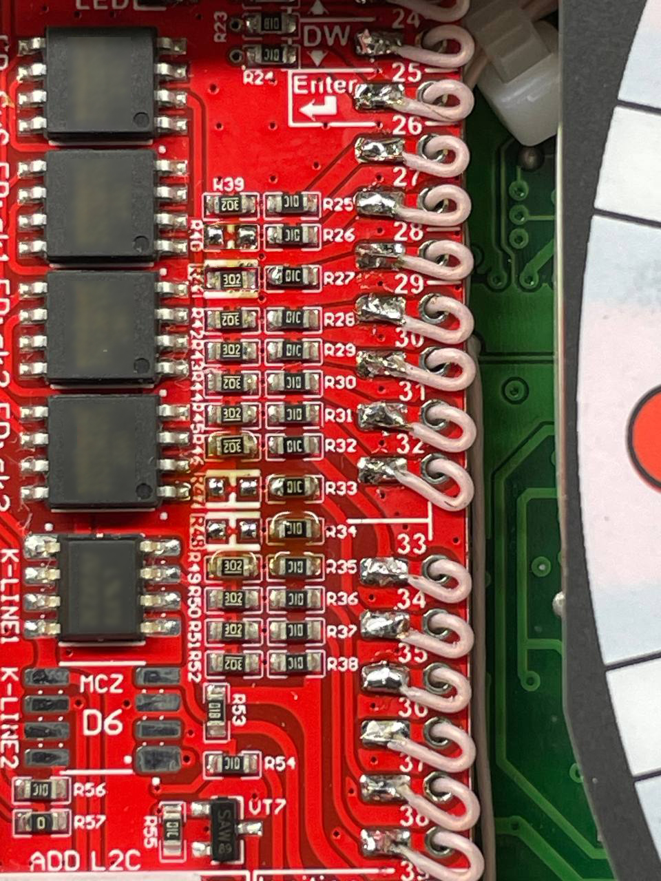
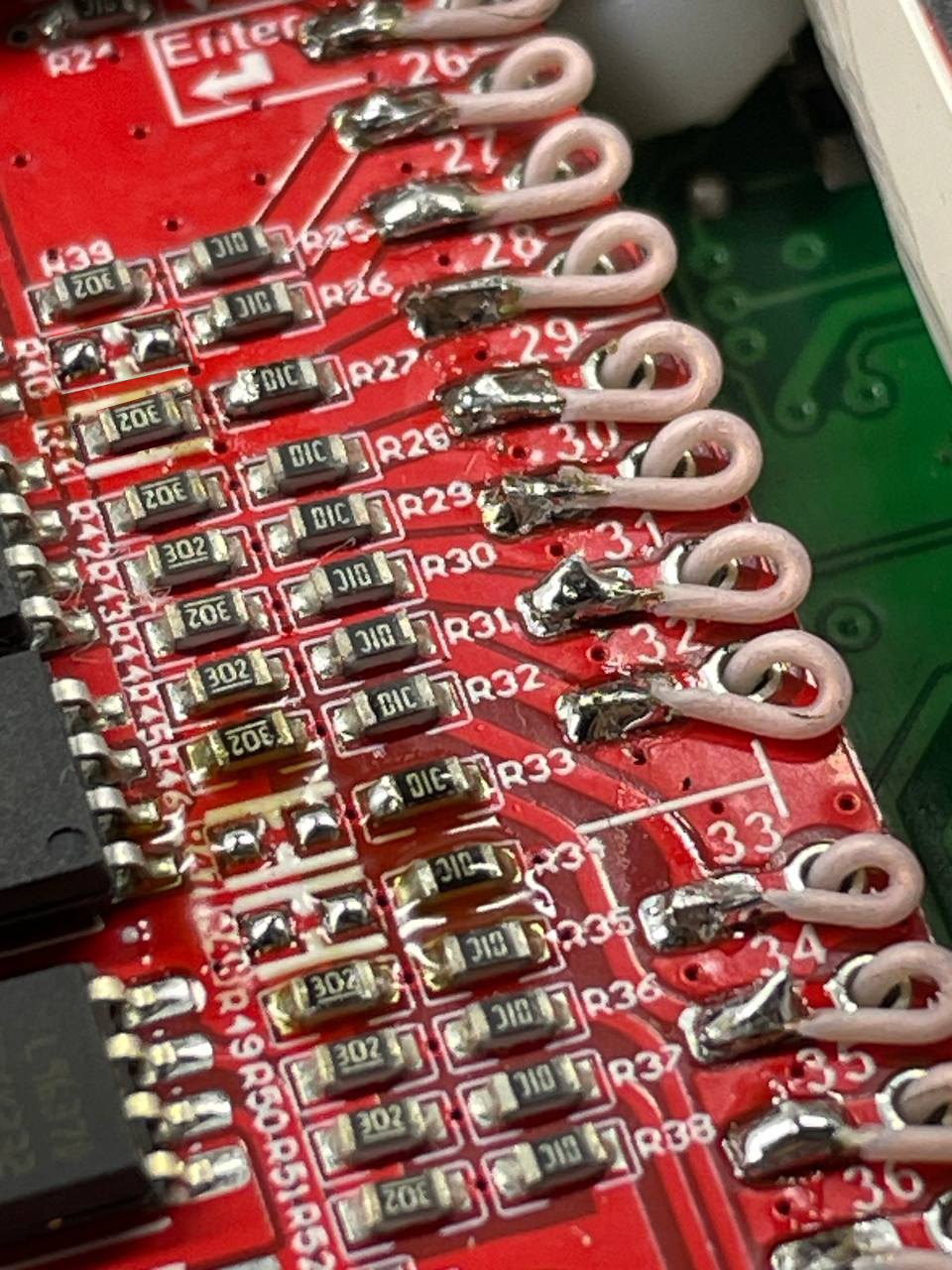
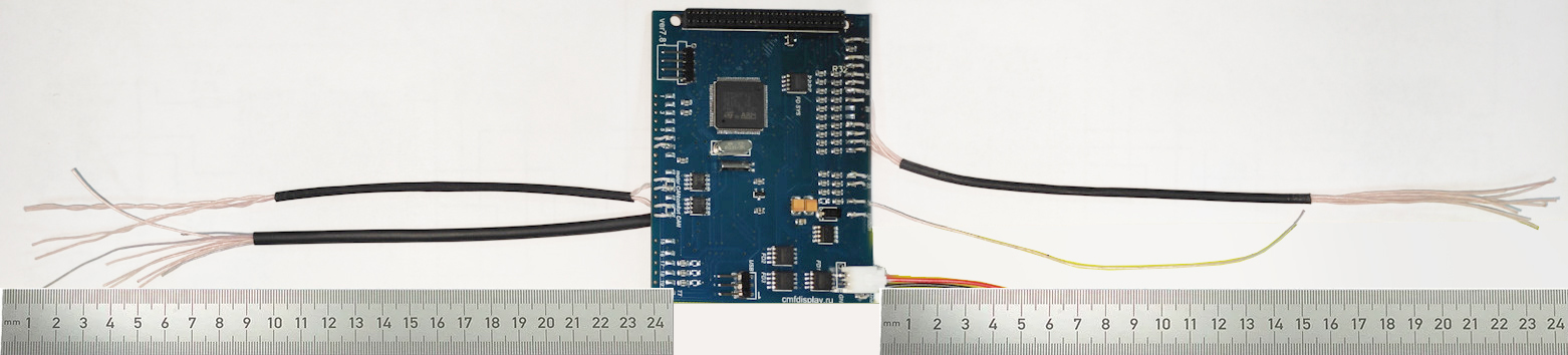
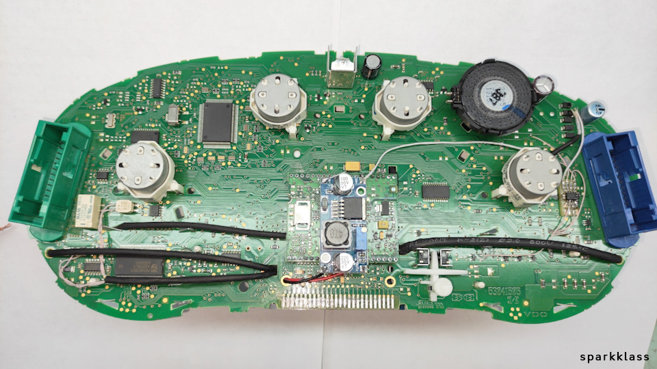
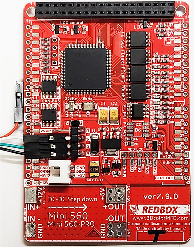
2.1. Remove LCD board from motherboard and Stretch the wires from MFD motherboard to the blue and green connectors through the holes in the cluster`s board. 2.1. Снимите ЖК-дисплей и протяните провода от материнской платы MFD к синему и зеленому разъемам через отверстия в плате кластера. |
|
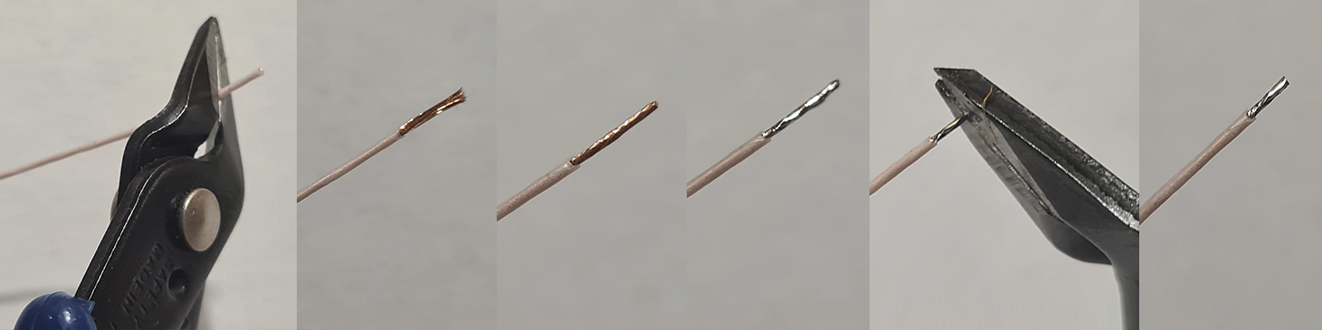
2.2 Start to soldering wires according to the table. Wires should be cleaned from Isolation, twisted and tin plated. 2.2 Приступаем к пайке проводов по таблице. Провода должны быть очищены от изоляции, скручены и залужены. |
|
2.3
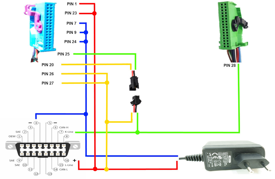
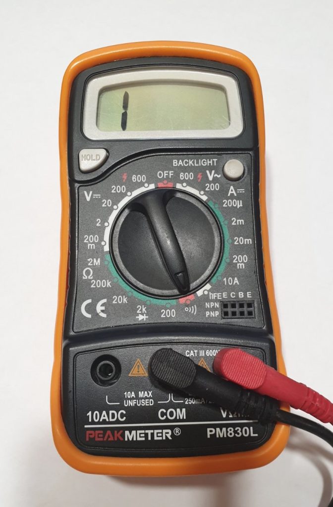
Take the multimeter, set it to Diode (Ring) mode. Using multimeter and wiring diagram, find the wires you need and solder them to the connector pins.
2.3 Используйте мультиметр,
установите его в режим диода (прозвонка)
и схему подключения, найдите нужные провода и припаивайте
их |
 |
NoFIS / HalfFIS


FullFIS

|
|
||||||||||||||||||||||||||||||||||||||||||||||||||||||||||||||||||||||||||||||||||||||||||||||||||||||||||||||||||||||||||||||||||||||||||||||||||||||||||||||||||||||||||||||||||||||||||||||||||||||||||||||||||||||||||||||||||||||||||||||||||||||||||||||||||||||||||||||||||||||||||||||||||||||||||||||||


|
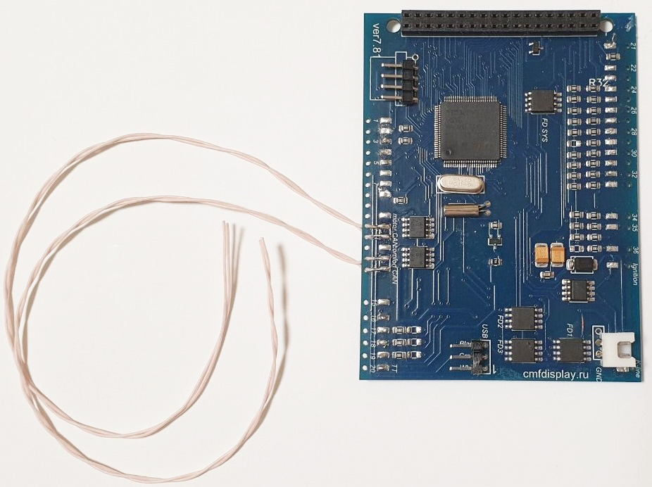
2.4. Twist in a spiral
CAN-bus connection wires.
2.4 Обязательно скручивайте в спираль
провода,
|
|
|
2.5.
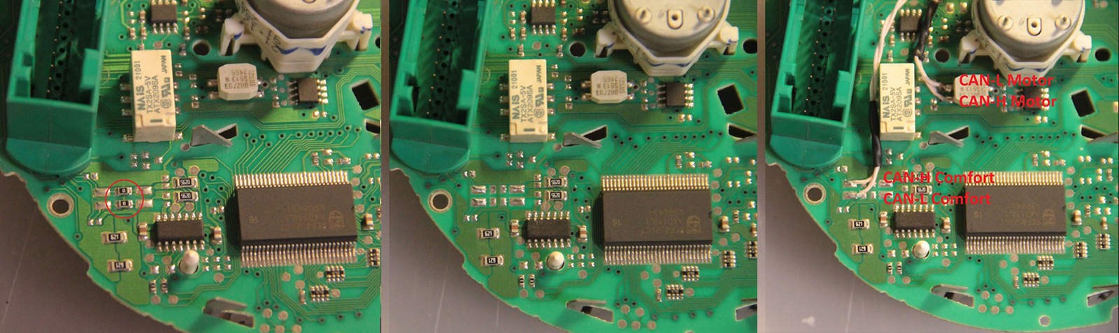
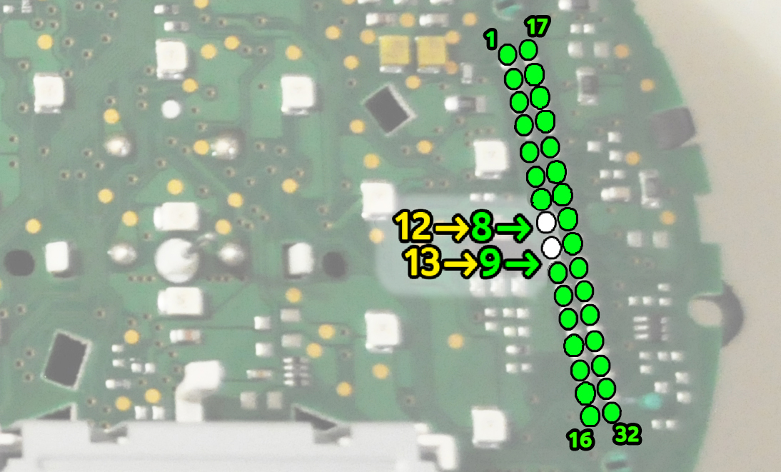
There are 2 ways to connect CAN bus wires. Choose what is
convenient for you. 2.5. Есть два варианта подключения проводов CAN-шины. |
|
1-st way: solder the wires to to the pins of the green connector 1-й вариант подключить провода к пинал разъема |
2-nd way: solder the wires to the points, indicated in the photo 2-й вариант подключить провода к точкам на тыльной стороне платы приборки. |
||
 |
 |
|
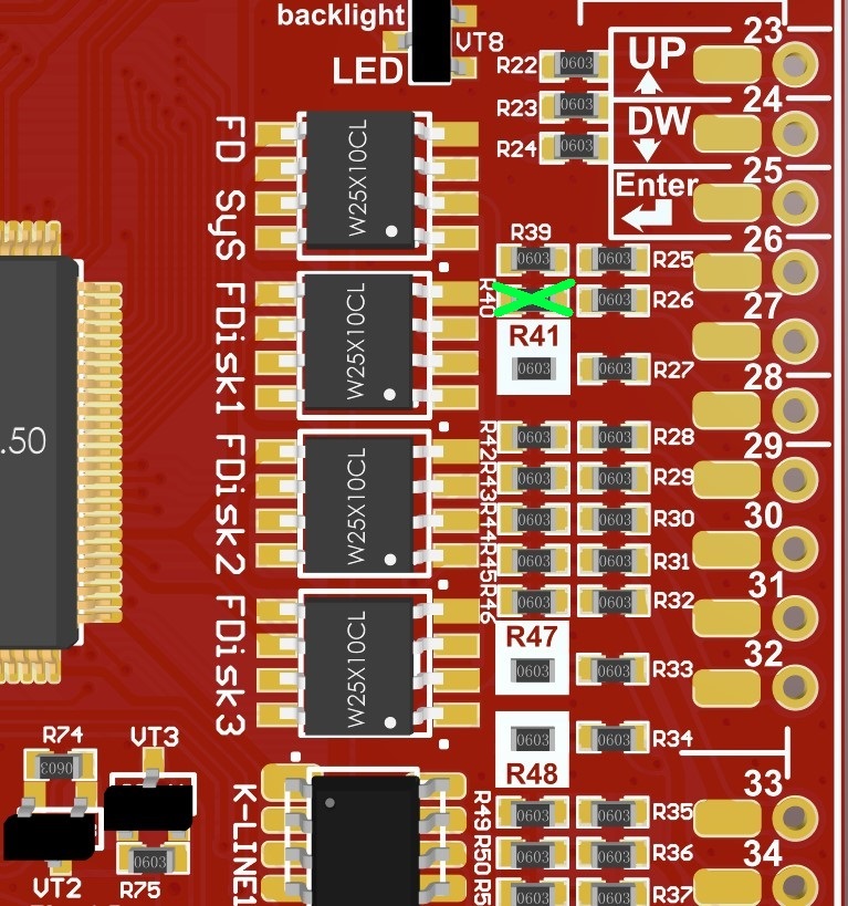
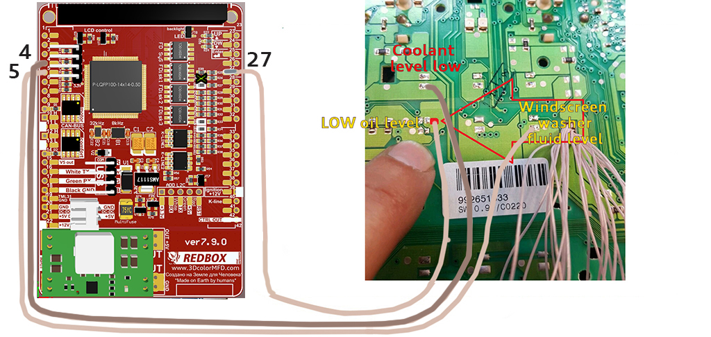
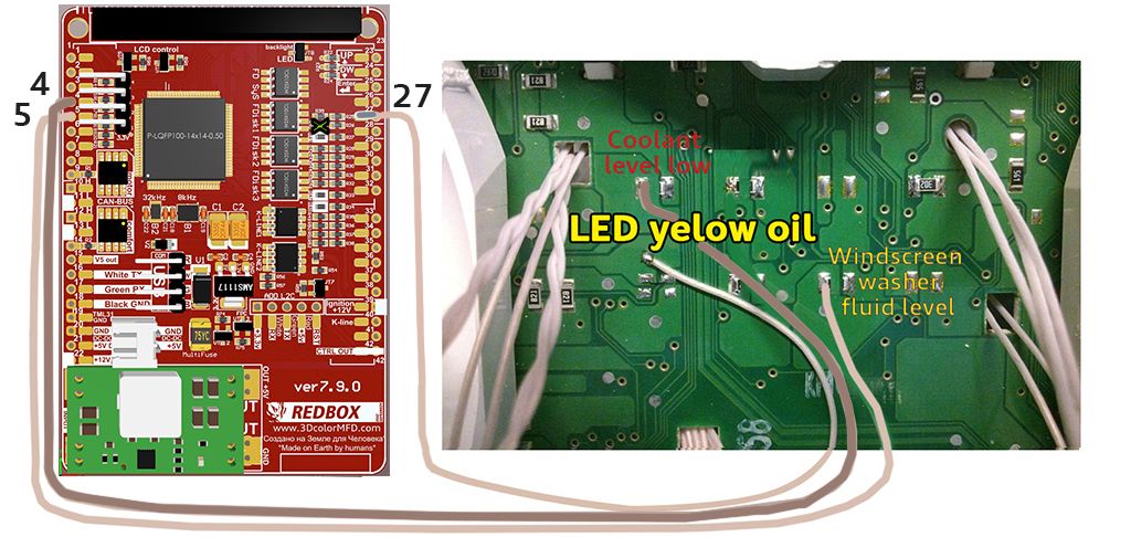
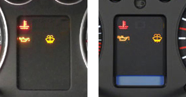
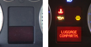
2.6. Important!If you have noFIS or halfFIS dashboard, you need to solder the wire from 27pin of MFD board to the LED`s cathod, on the dashboard. And you need to remove 3kOhm (302 or 3001) resistor from 27pin of MFD board.
2.6. Важно! |
|
|
2.6.
noFIS
|
|
|
2.6. halfFIS
|
|
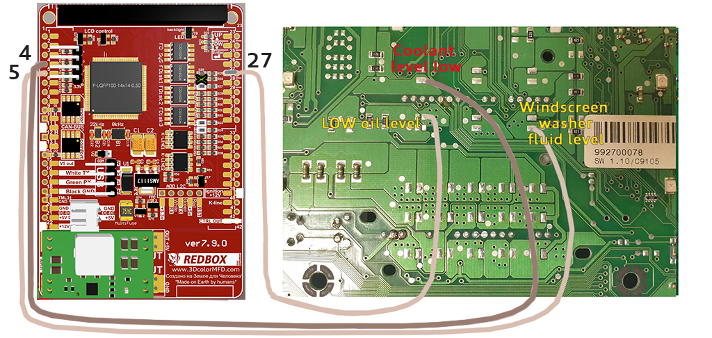
|
2.6. fullFIS
|
|
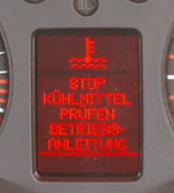
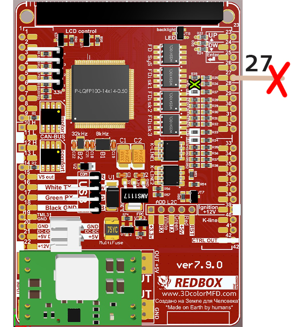
|
После установки необходимо подключить MFD к программе Shell и настроить предупреждение о низком уровне масла для кластера FullFIS как показанно ниже на картинке.
Shell program link:
Video instruction:
|
|
|
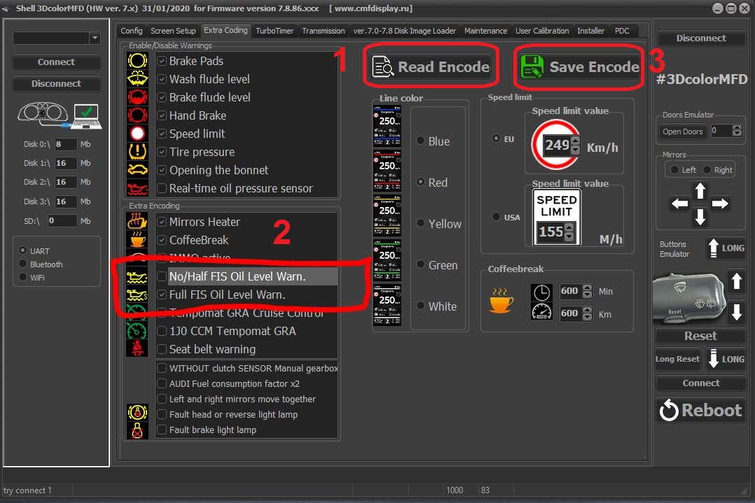
|
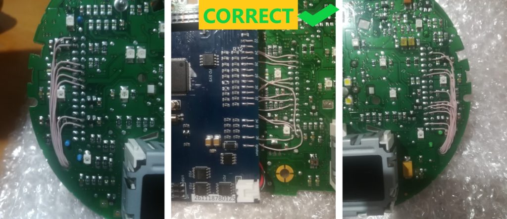
2.7. Lay the wires in such a way that they do not interfere with the installation of white Light diffuser. 2.7. Провода следует тянуть с тыльной стороны или, как показано выше,так чтобы при сборке приборки провода не мешали. |
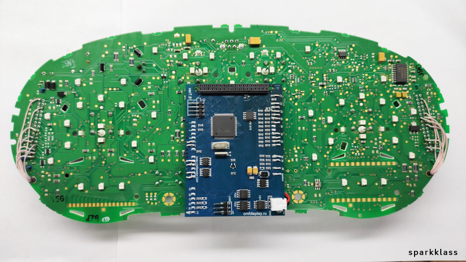
|
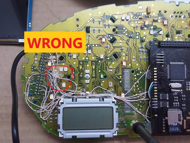
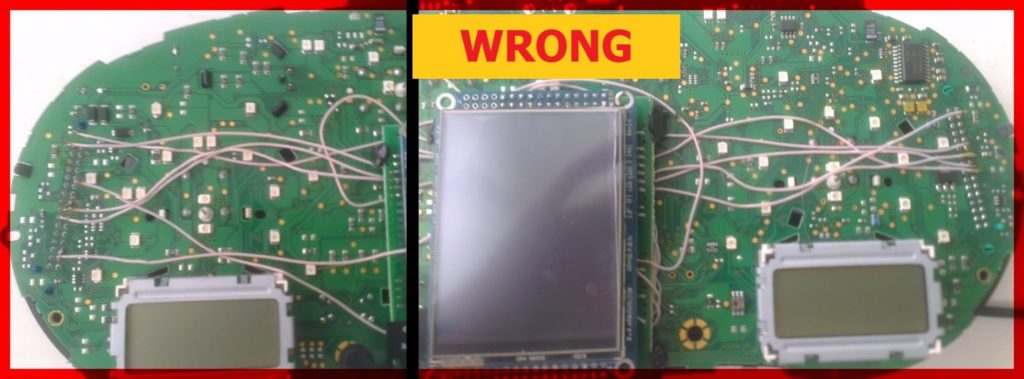
2.7. Wires should be pulled from the back side Or as shown above, so they do not interfere with the assembly of the device. So it's not right!
2.7. Провода следует тянуть с тыльной стороны или, как показано выше,так чтобы при сборке приборки провода не мешали.
|
 |
|
 |
|
Attention! 2.8 There are several types of DC-DC converters
ВНИМАНИЕ!
|
|
#1 |
#2 | #3 | #4 |
|
|
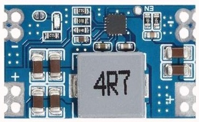 |
 |
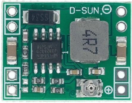 |
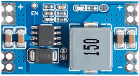
|
|
|
|
#1 This type of DC-DC converter is already set to 5.2V Этот тип DC-DC конвертер уже настроен на 5.2В
|
|
#2 This type of DC-DC converter is already set to 5.2V Этот тип DC-DC конвертер уже настроен на 5.2В
|
|
|
|
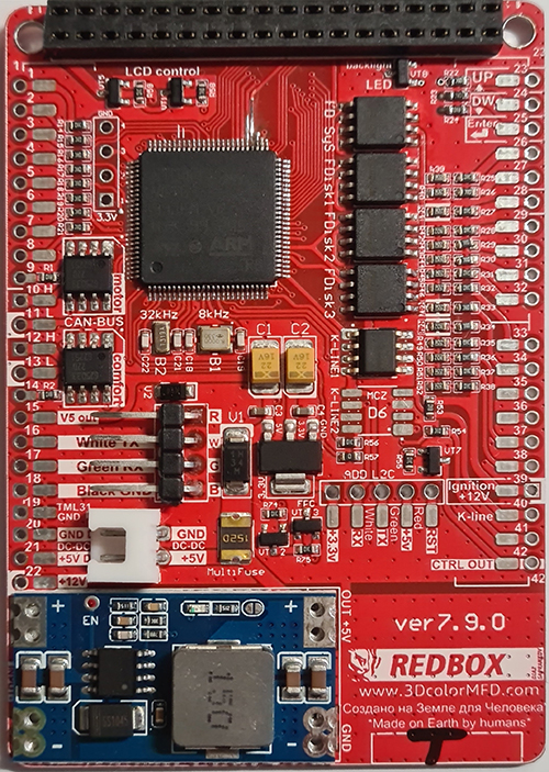

|
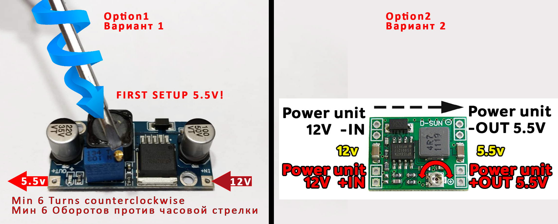
Attention! 2.8. Before installing the power supply, you need to solder the wires to it contacts + IN - IN and + OUT - OUT, then apply a current of 12V to + IN - IN, and connect the + OUT - OUT wires to the tester. Now we need to adjust the output current. Using a small flat screwdriver slowly rotate the special metal knob (figure 1 in the picture.) Clockwise Arrow, until, at us on the tester will not appear 5,5v in an output voltage. Next we place the power supply unit on the back side, we bring to its contacts the wires from the blue connector.
9
pin of blue
GND connector is connected to the e - IN on
the power supply board.
ВНИМАНИЕ! затем подайте ток 12 В на + IN - IN и подключите провода + OUT - OUT к тестеру. Теперь нам нужно настроить выходной ток. С помощью небольшой плоской отвертки медленно поверните специальный винт (цифра 1 на рисунке) по часовой стрелке много раз, до тех пор, пока, у нас на тестере не появится +5,5v в выходном напряжении. Далее размещаем блок питания с тыльной стороны, подводим к его контактам провода от зеленого разъема. 9 контакт синего разъема - GND подключен к разъему e-IN на плате блока питания. 23 контакт синего разъема +12V подключен к + IN на плате блока питания,
|
|
|
 |

|
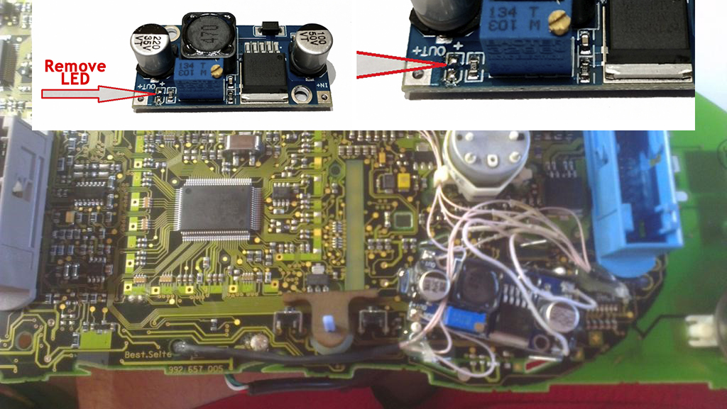
2.8. Connect - OUT Connects to 20 pin MFD Choose the place of installation of the power supply so that during assembly it does not interfere. Here are the possible
2.6. Соедините
|
|
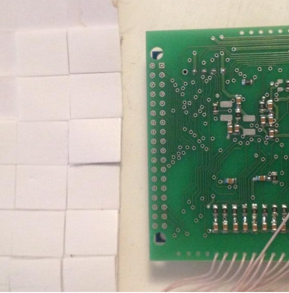
3. We take
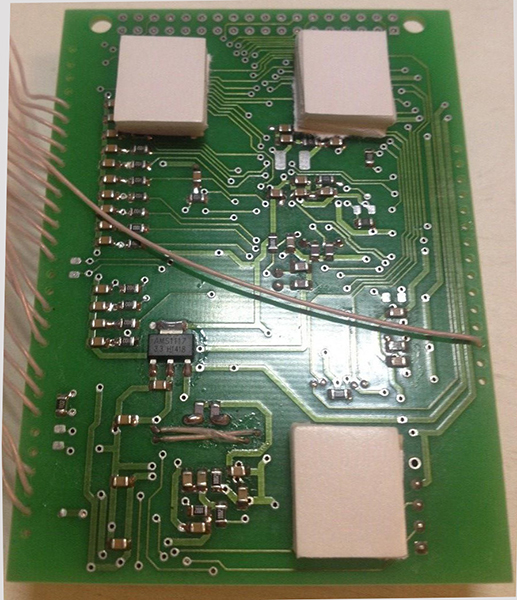
double-sided adhesive tape on a foamy basis, cut the squares 1cm X 1cm.
3. Берем двусторонний скотч и вырезаем квадраты 1см Х 1см. |
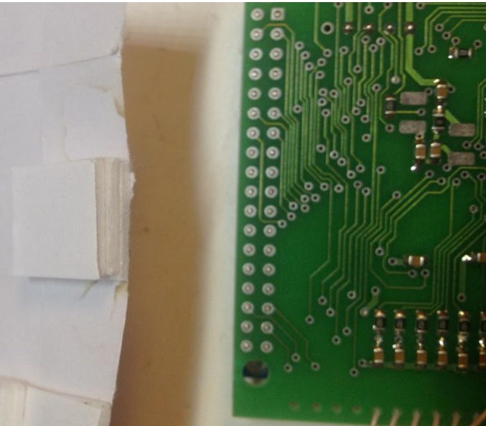
3.1. We collect these squares in 3 floors.
3.1. Собираем скотч в 3 слоя. |
 |
 |
|
3.2.
And we place it on the
3dMFD board, the height of the adhesive tape should be enough so
that the 3dMFD board does not touch the cluster board. 3.2. И размещаем на плате 3dMFD, высоты скотча должно быть достаточно, чтобы плата 3dMFD не касалась платы приборки. |
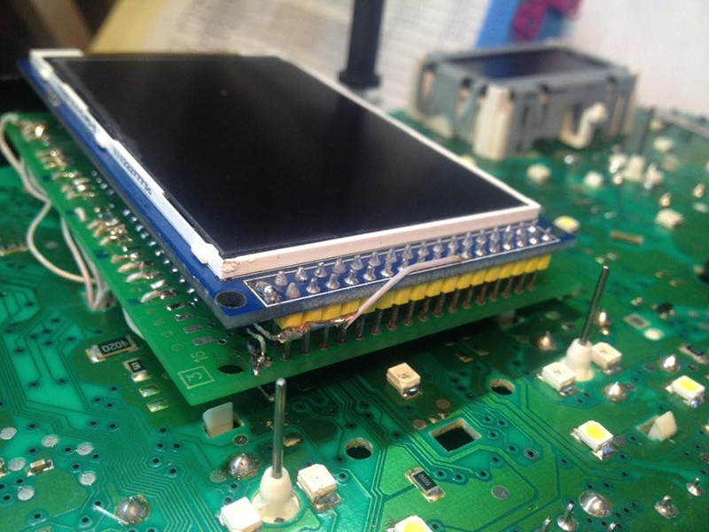
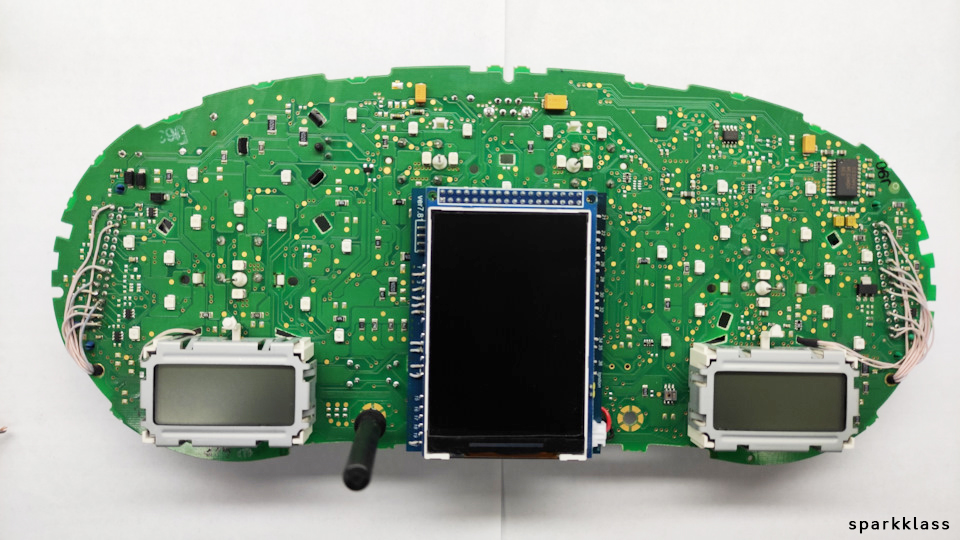
3.3. Place the module so that it is placed in the window of the device 3.3. Разместите модуль так, чтобы он находился в оконе маски приборки. |
 |
 |
|
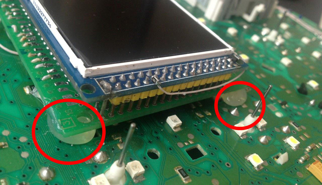
3.4.
For greater reliability, when the module is already installed on the
board,
and you calibrated it in the window so that there were no distortions, it is better to fix it. Its hot glue along the edges of the module.
3.4. Для большей надежности, когда модуль уже установлен на плате, а вы откалибровали дисплей так чтобы не было перекосов, вы можете зафиксирвать палту 3dMFD горячим клем по краям модуля. не нужно заливать полностью всю плату в 2 -3 точках будет достаточно. |
|
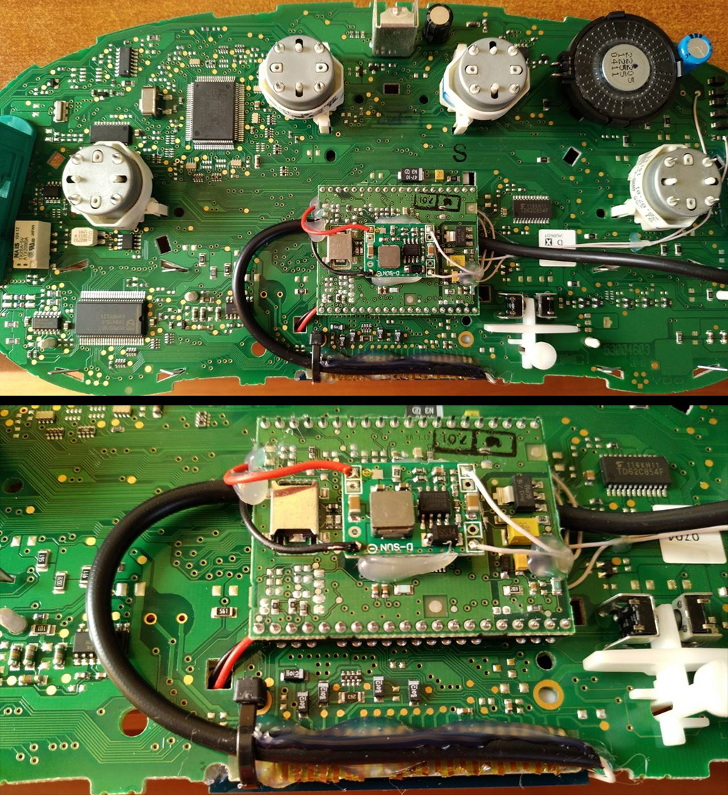
4. The USB
cable should be fixed with glue. Red USB wire do not use, cut it off.
4. Кабель
USB следует закрепить клеем. |
|
4.1.
BETTER
USB connection option, you must solder the wires to the board.
4.1. Предпочтительный вариант подключения USB, вы должны припаять провода к плате. |
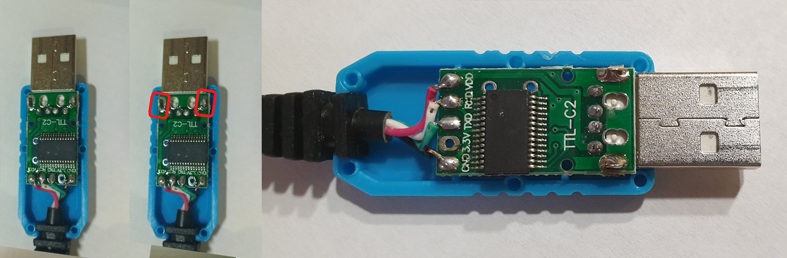
4.1.Acceptable
USB connection option, you can use the connector.
4.1. Допустимый вариант подключения USB, вы можете использовать разъем для подключения. |
 |
 |
|
4.2.
OpenUSB
And solder
the metal ears marked in red.
4.2. Откройте USB и припаивайте металлические уши отмеченные красным |
|
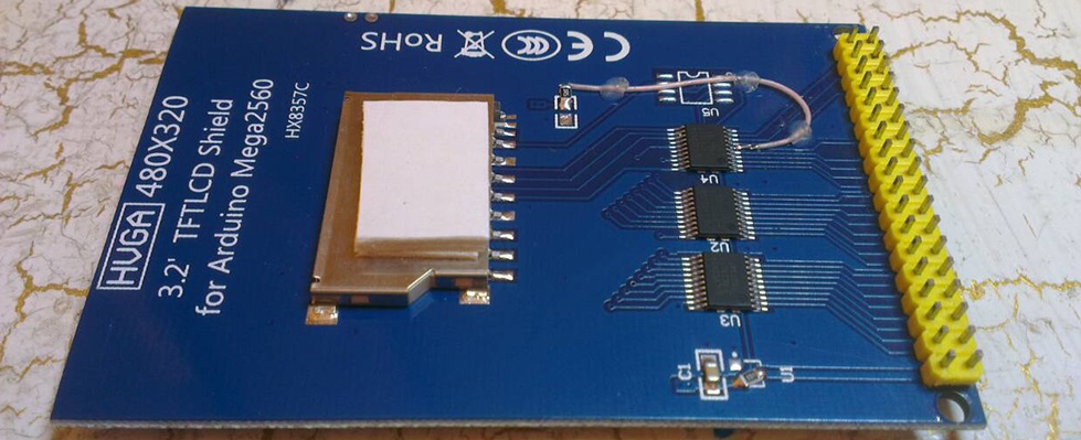
5.
Before installing the display, you need to glue double-sided
adhesive tape into three layers on the back of the display to lock
the display.
5. Перед
установкой дисплея нужно приклеить двухсторонний скотч, для того
чтобы создать дополнительную опору |
|
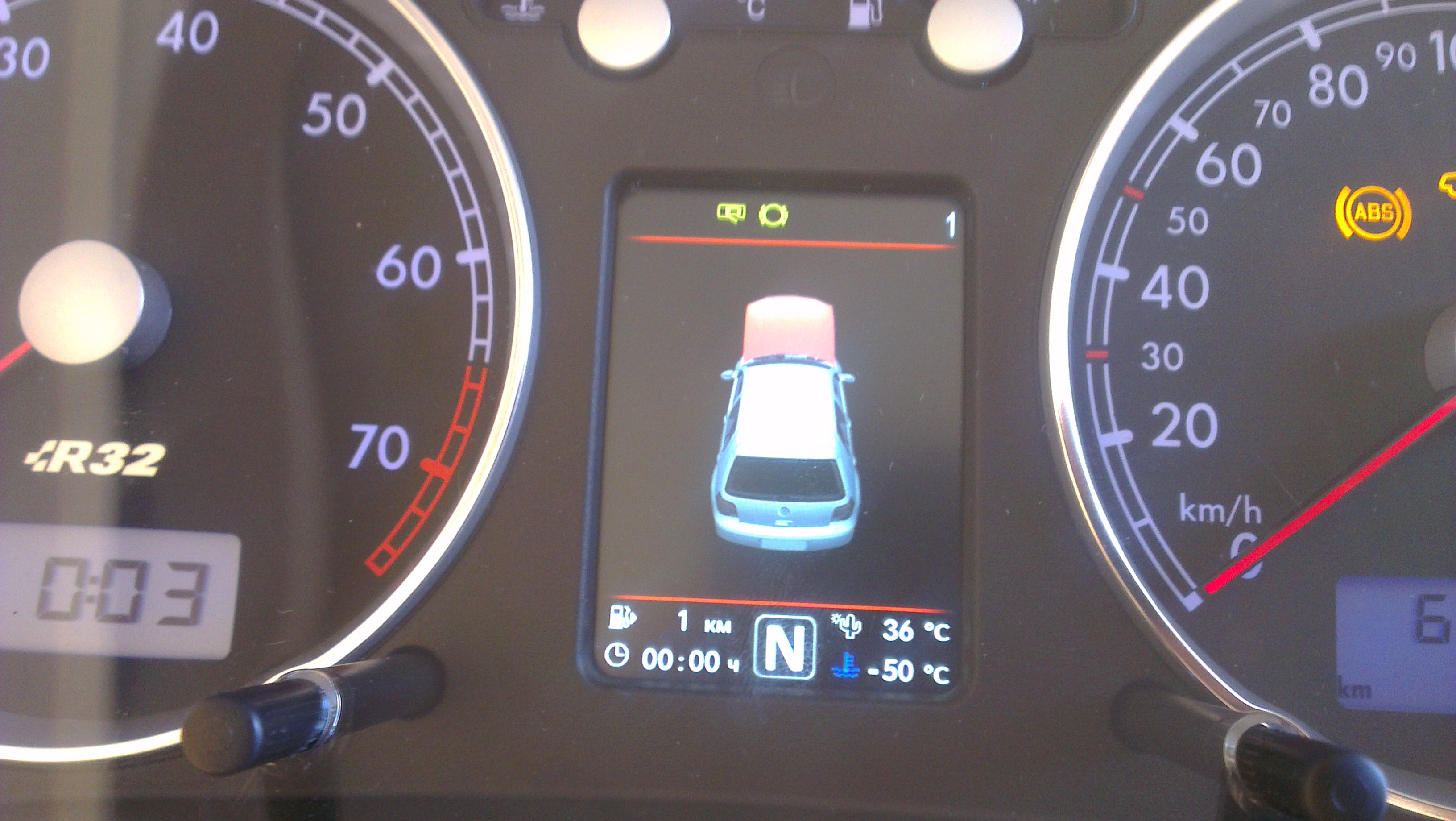
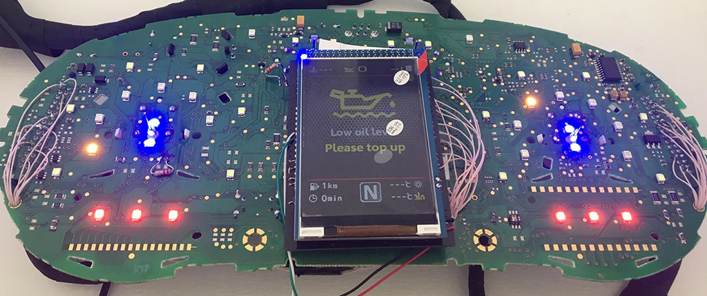
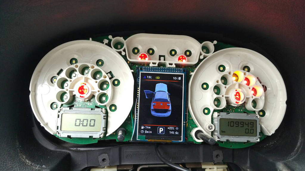
6. After you solder the wires and set the display to its place, you need to test the 3dMFD performance in the car to make sure everything is properly installed and working well.
6. После того, как вы припаяли все провода и установите дисплей на место, вам необходимо протестировать работу 3dMFD в автомобиле, чтобы убедиться, что все правильно установлено и работает нормально. |
|
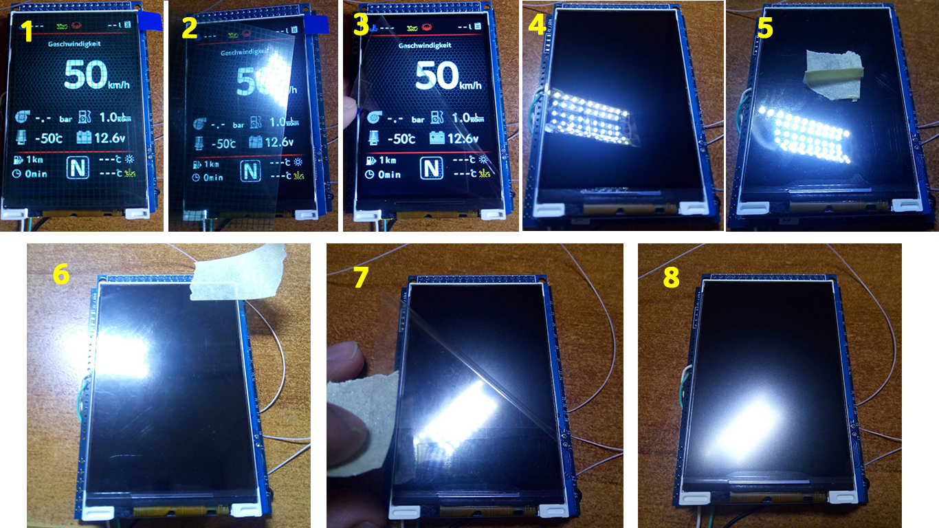
7. Next, you
need to glue the matte protective film so that the display does not
glare in the sun. Unfortunately, the film may not always be included, but it is easy to find on Marketplace, you can use a polyurethane matte screen protector for any smartphone just cut out with scissors to the right size.
7. Далее нужно приклеить матовую
защитную пленку, чтобы дисплей не бликовал на солнце. |
|
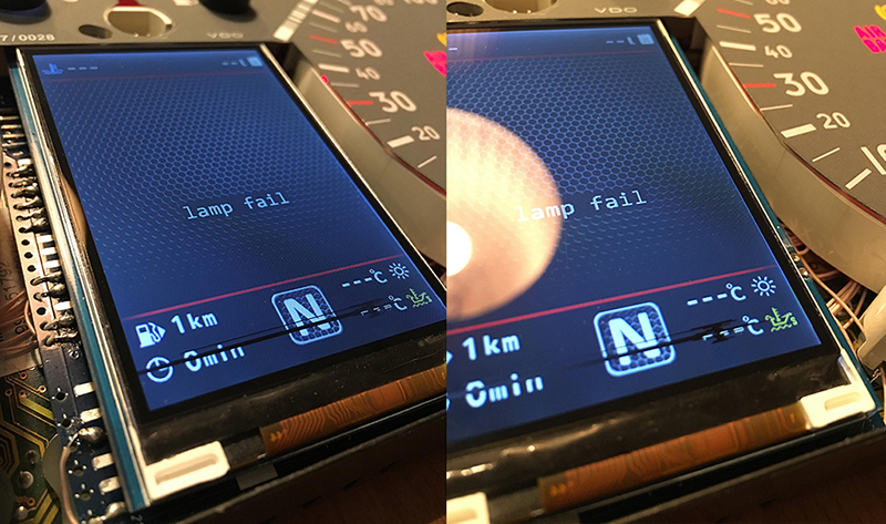
Attention!
Be sure to stick the film!
Внимание!
Обязательно наклеить защитнкю матовую пленку
на дисплей! |
|
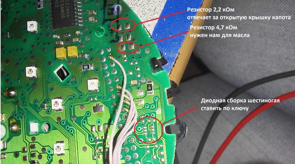
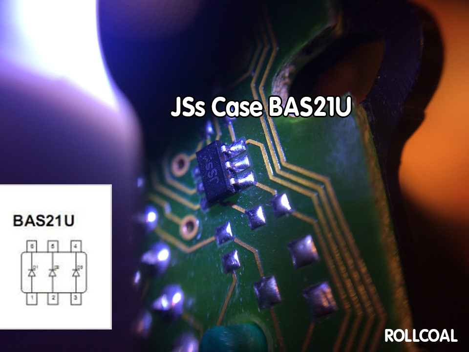
8. If you are the lucky owner of Passat B5, released for USA market, you have to add a few SMD resistors to the dashboard.
In clusters for the American market, there are no open hood and
oil level control resistors, and there are no oil level and
temperature sensors in the engine sump. 8. В приборке выпущенного для рынка США нет индикации открытого капота и резисторы контроля уровня масла, а в поддоне двигателя отсутствуют датчики уровня и температуры масла. Вам придется добавить на приборную панель несколько SMD-резисторов. |
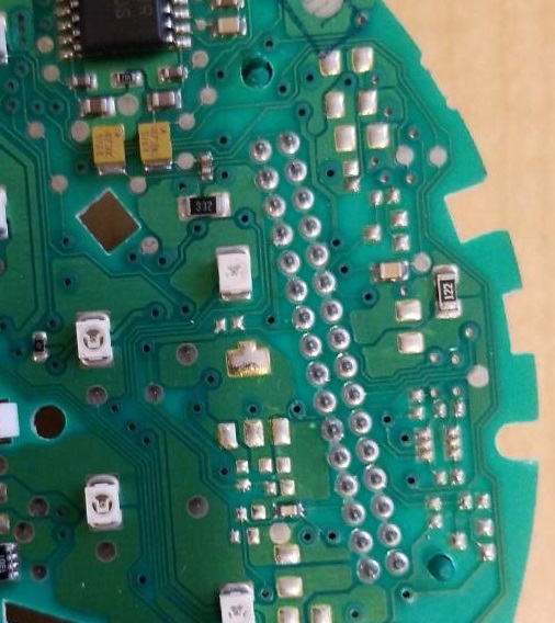
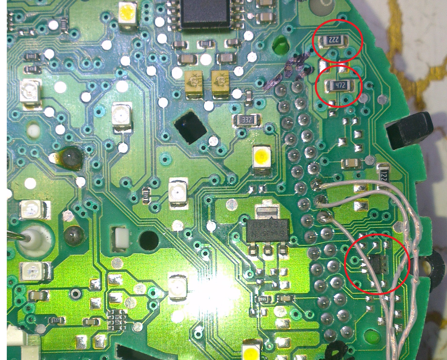
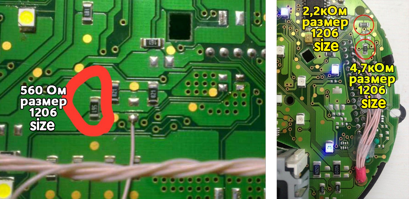
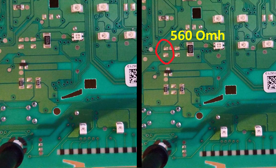
|
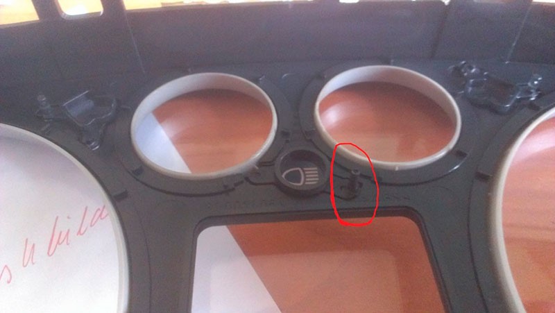
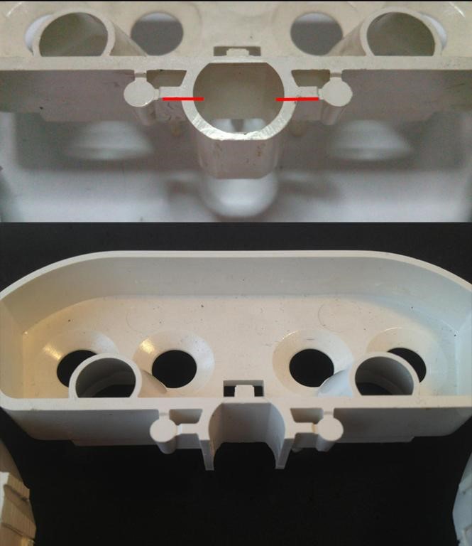
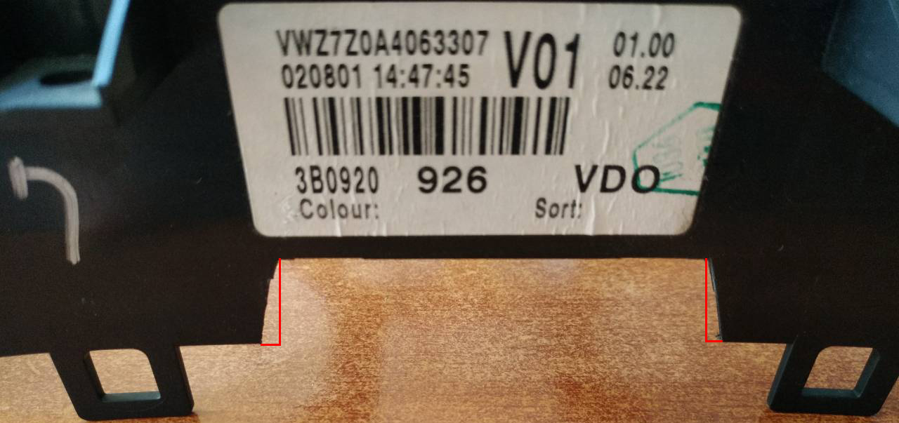
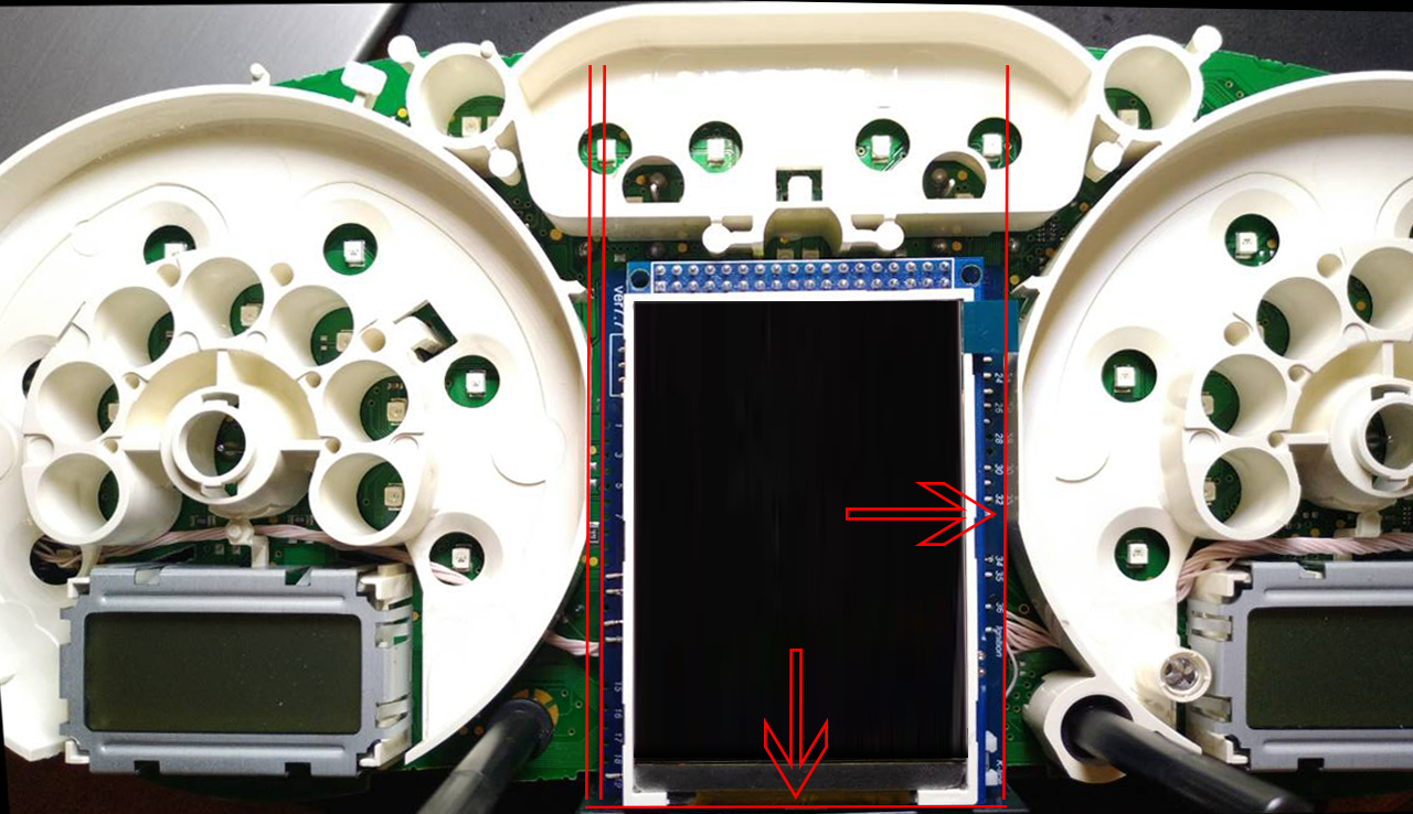
9.1. Cut off the main beam guide part. On the red line. Leave the semicircle. 9.1. Отрежьте пластик как показано на фото |
9.2. Cut off the protruding part!
9.2. Отрежьте пластиковый
штырь |
|
|
|
|
|
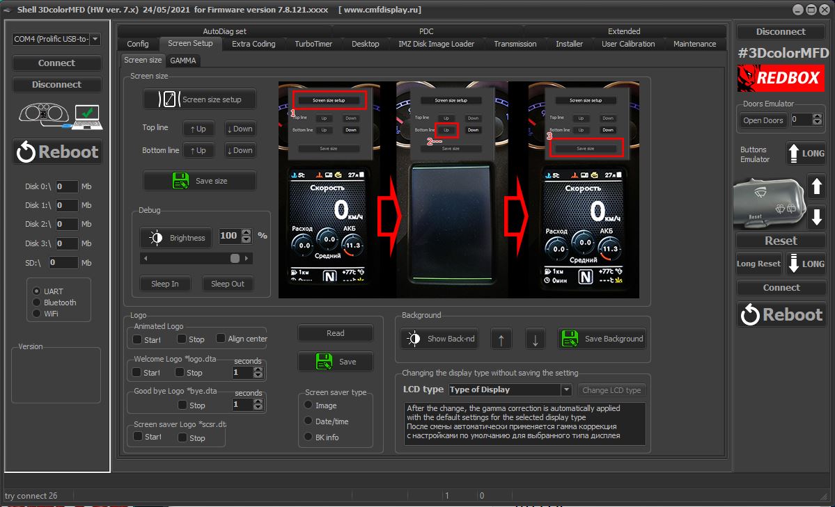
9.3.Using the Shell -> Screen Size program,
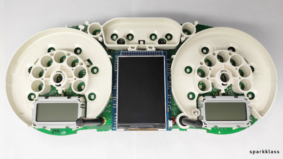
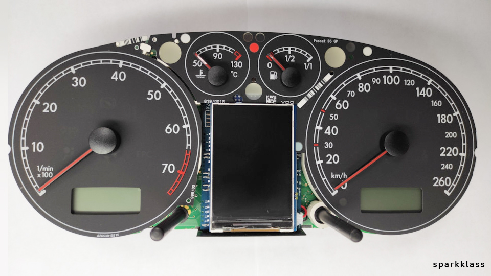
adjust the display frames according to the window in the tidy scale. 9 .3. С помощью программы Shell -> Screen Size настройте рамки дисплея по окну в шкале приборки. |
|
11. boost pressure control11. Подключить отображение давления наддува
|
|
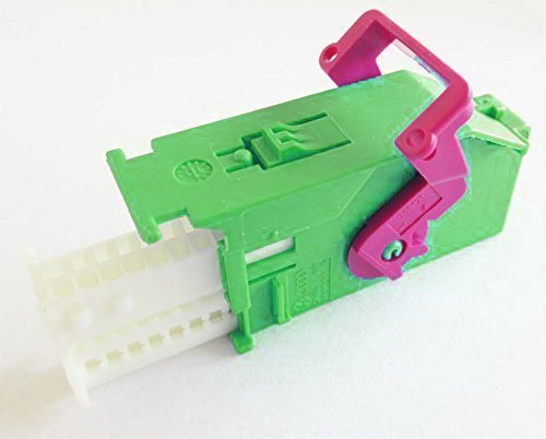
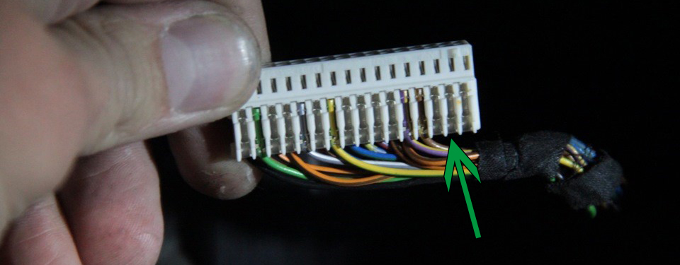
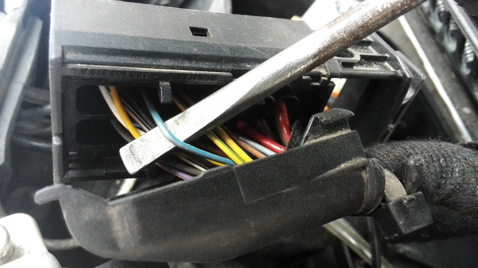
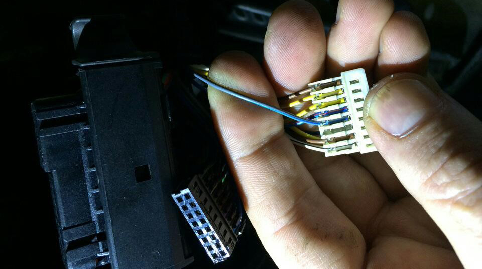
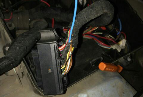
11.1. T o connect the boost pressure control, you will need to add one PIN to the dashboard 15pin green connector. The photo below is for example.
11.1. Чтобы подключить отображение давления наддува, вам нужно будет добавить провод от ЭБУд к 15-му PIN зеленого разъема приборки. Фото ниже приведено для примера. |
|
|
11.2.
And the other end of the wire needs
to connect the signal wire of the boost sensor to the engine ECU.
11.2. А второй
конец провода нужно подключить сигнальный
провод датчика наддува в ЭБУдвигателя.
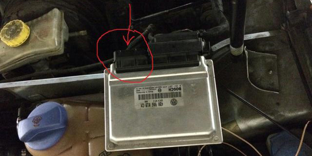
|
|
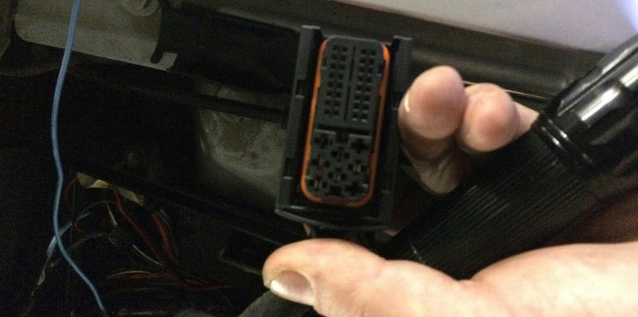
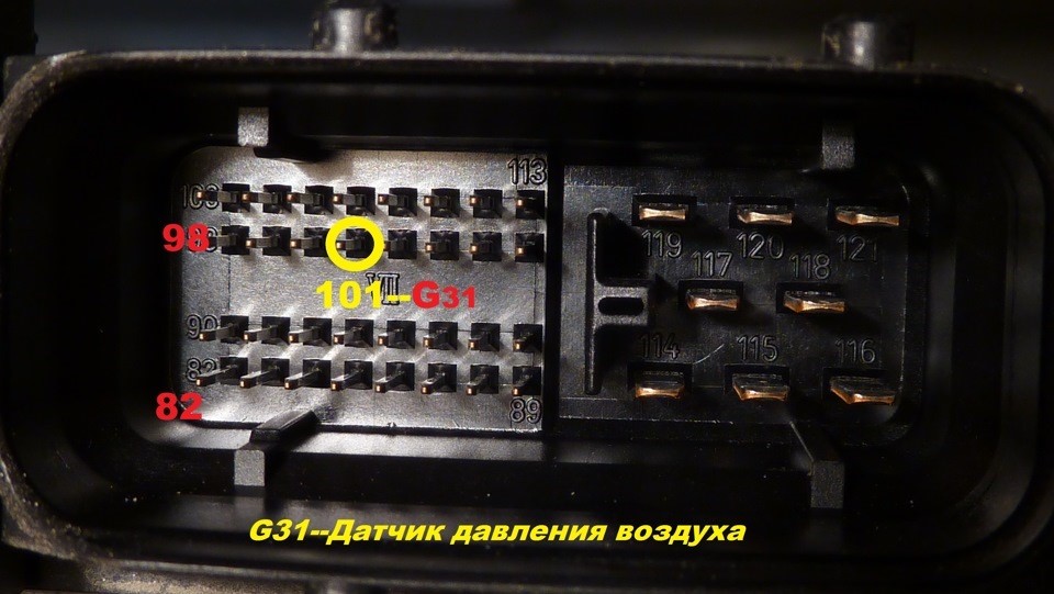
11.3. Usually it is blue - gray wire (blue with a gray bar) to the incoming on the 101st contact of a smaller brain connector. (for a gasoline engine)
On diesel
engines (AVB and others):
On petrol
(AWM and others): In general, as far as I understand, at all B5-x diesel 1.9T supercharging is connected to the 71st and the gasoline 1.8T is connected to the 101st contact. The color of the wire can vary depending on the year / engine.
8.3. Чаще всего со стороны ЭБУД к сине-серому проводу (синий с серой полосой) приходящемуна 101-й контакт меньшего разъема мозга. На дизелях (AVB и других): — 71-й контакт моторного мозга, зелено-красный провод (зеленый с красной полосой). На бензиновых (AWM и других): — 101-й контакт моторного мозга, провод (серый с си&# 1085;ей полосой). Отличаться может цвет провода в зависимости от года/двигателя.
|
|
 |
 |
 |
|
 |
 |
 |
|
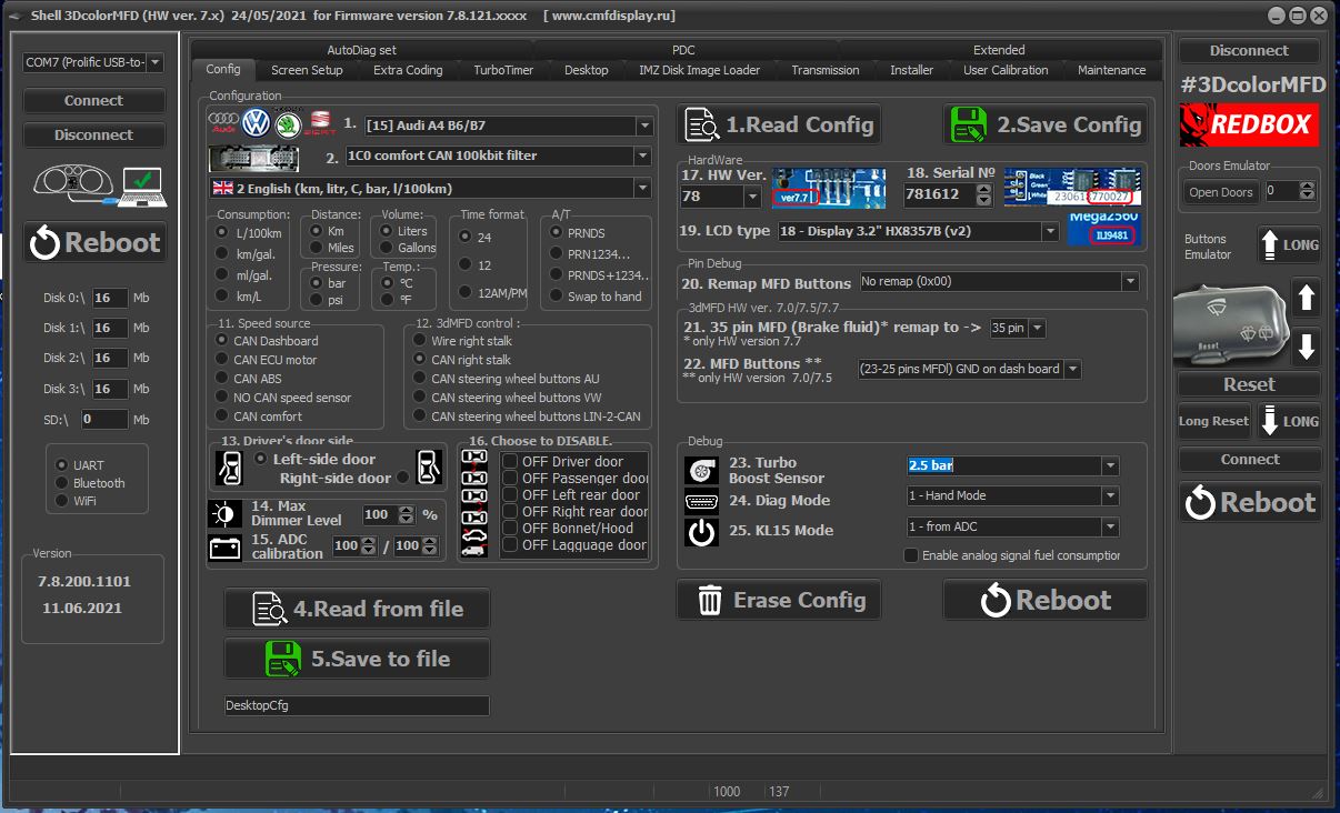
11. После того как вы проложили сигнальный провод от ECU двигателя к приборке сделайте настройку в программе Shell, для того чтобы 3dMFD отображал давление наддува турбины. Вы должны установить тип вашего датчика давления, это можно сделать опытным путем подбирая его по списку в Шелл программе. |
|
11.12 Controls: |
11.12
Управление: Для упраления 3dMFD нужно добавить недостающие пины, для этого можно использовать штатный точки. |
|
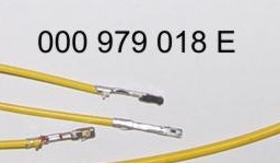
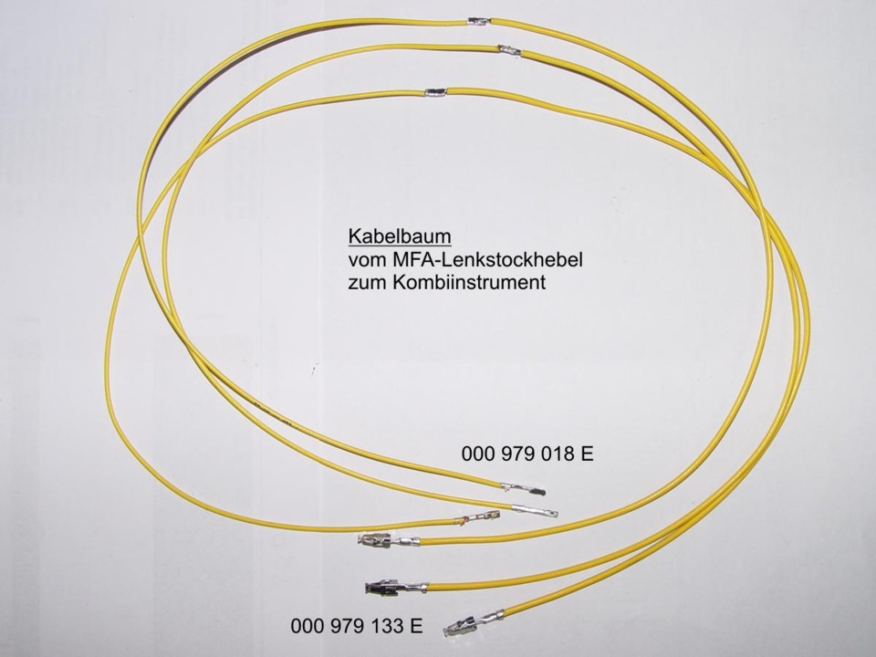
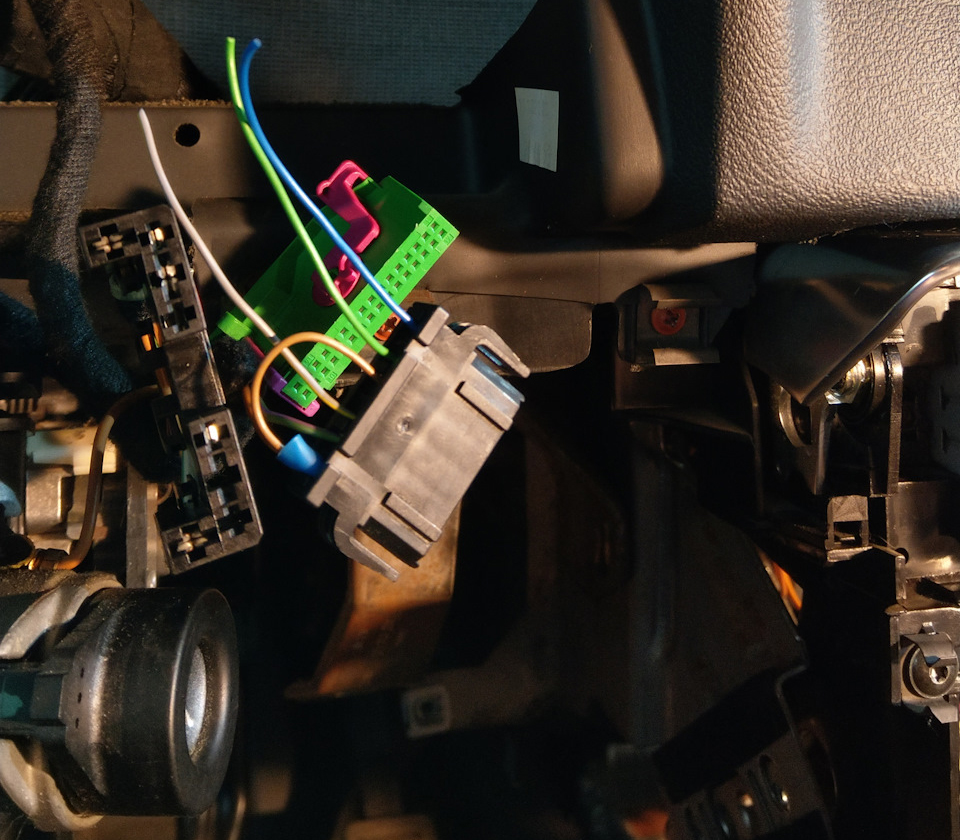
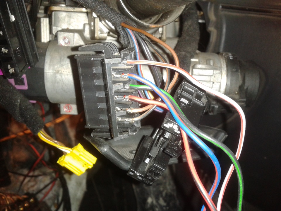
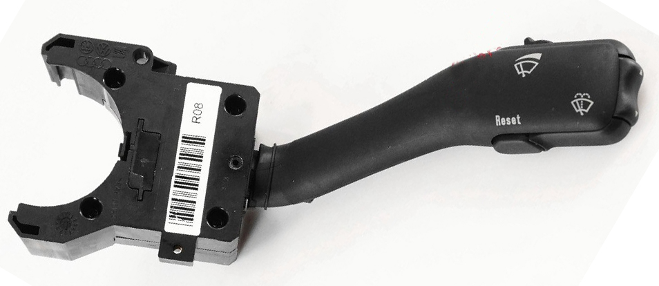
Connecting the steering wheel switch: switch connector / dash
connector 000979018E, 000979133E |
Подключение подрулевого переключателя: разъем переключателя / разъем
приборки Подключение подрулевого переключателя: разъем переключателя / разъем приборки 1 — 23 зеленый разъем приборной панели ВВЕРХ 2 — 24 зеленый разъем приборной панели ВНИЗ 3 — GND синий разъем приборной панели 4 — 25 зеленый разъем приборной панели РЕСЕТ 000979018E, 000979133E |

|
12. Assembly. And then we collect everything in the reverse order without forgetting to calibrate the needles with the help of the WAG-com.
12. СБОРКА. Собирайте все в обратном порядке, не забывая калибровать иглы с помощью программы VAG-com.
|
|||
|
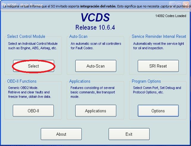
12.1. To do this, connect the device to the machine without installing the glass, connect the VAG-com.12.1 Для этого установите приборку в автомобиль (без стекла) и подключите его VAG-com. |
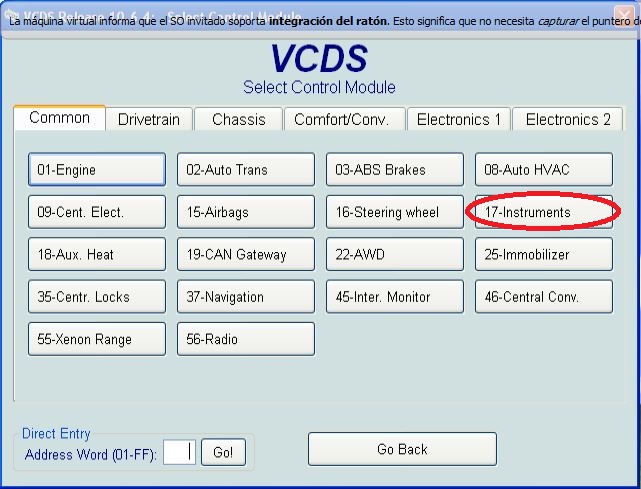
12.2. Go
into the 17-unit dash panel 12.2 Зайти в 17-блок панель приборов |
||
|
|
 |
|
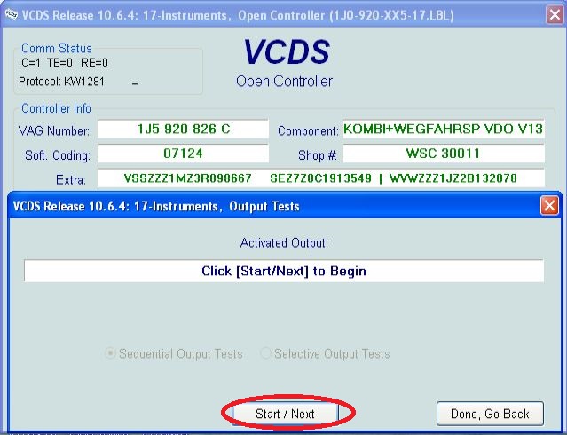
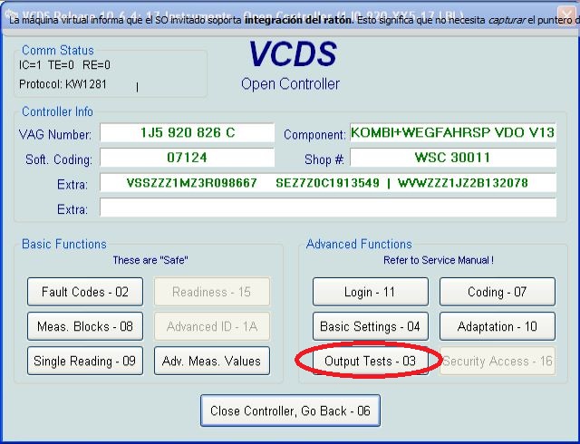
12.3. Select test performers. 12.3. Выбрать "Тест исполнителей".
|
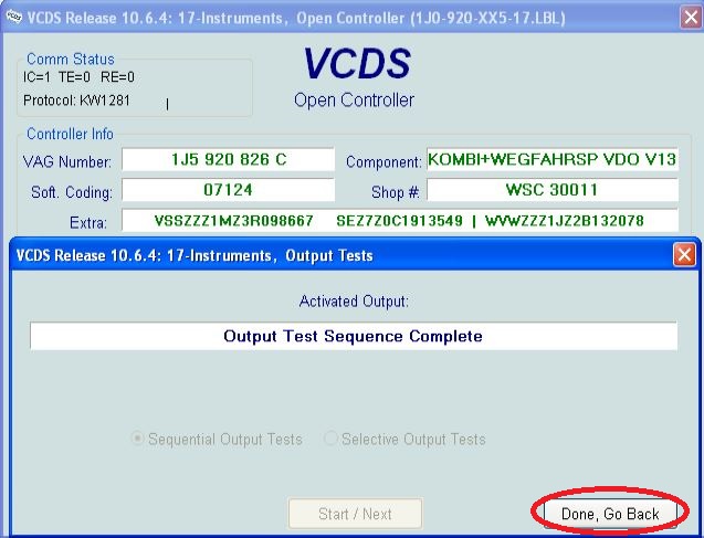
12.4. Choosing in turn a tachometer, temperature and the rest, the arrows in turn will be Do a turn on the whole scale, and then freeze on:
12.4 Сделайте тест стрелок.
|
|
|
 |
|
|
|
|
|
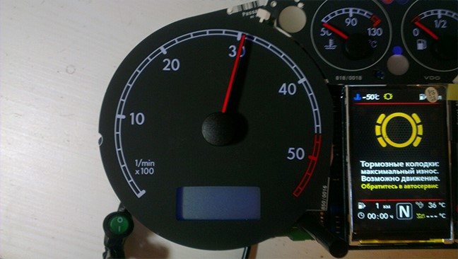
12.5. Tachometer - 3 thousand revolutions 12.5. Тахометр - на 3 тыс. оборотов |
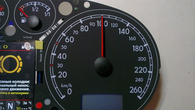
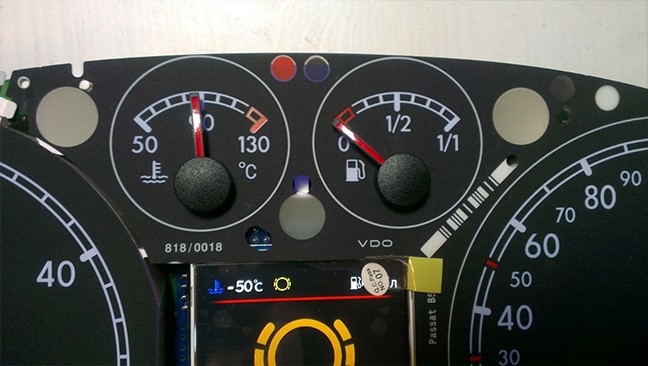
12.6. Pace. Coolant - middle 12.6. Спидометр - на 100 км/ч |
|
|
 |
|
12.7. Fuel level - middle 12.7. Уровень температуры ОЖ - по средине |
12.8. Speedometer - at 100 km / h 12.8. Уровень топлива - по средине |
|
|
 |
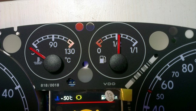
|
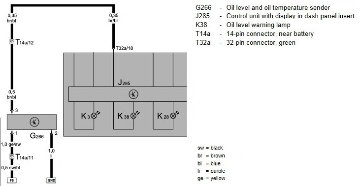
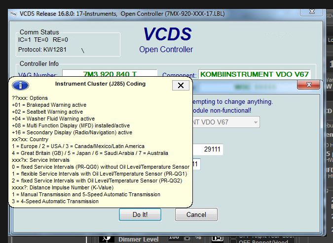
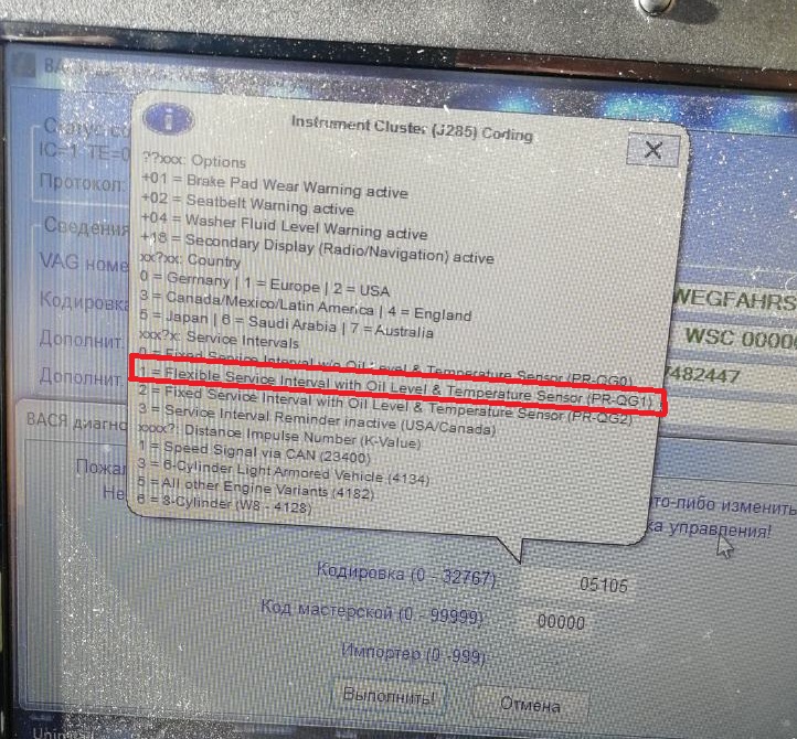
If your oil level is not working |
|
|
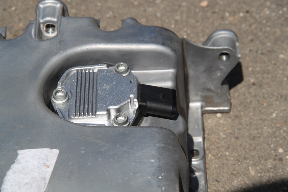 |
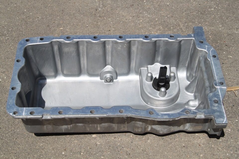
|
|
 |
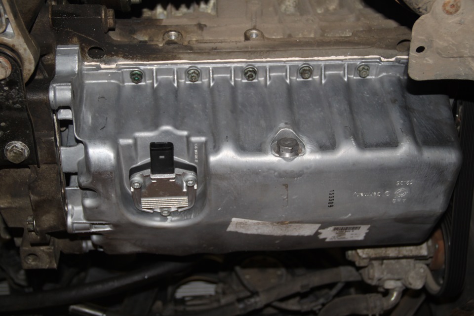
|
|
|
|
 |
|
Then check everything again
|
|
Затем проверьте все снова Вы не можете поворачивать стрелки слишком быстро, исправляя положение, вы можете повредить двигатели стрелки, а так же нельзя поворачивать стрелки при включенной приборке.
|
|
P.S. In cars with manual gearbox,
the ECU has no information about which gear you have selected, and
3dMFD cannot read it, |
|
P.S.
В автомобилях с механической коробкой передач ЭБУ
двигателя не имеет информации о том, какую передачу вы
выбрали, |
|
|
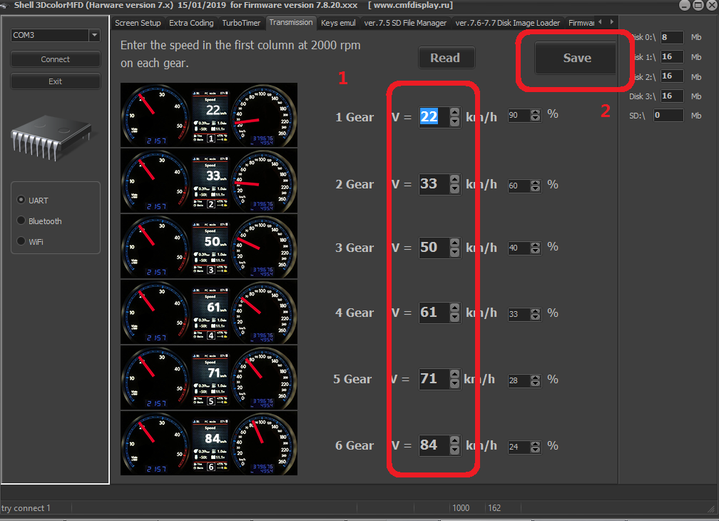
|
If the N signal does not appear when the clutch pedal is depressed. Check the settings in the Config tab
|
|
Если при нажатии на педаль сцепления не появляется сигнал N. проверте настройки во вкладке Конфиг |
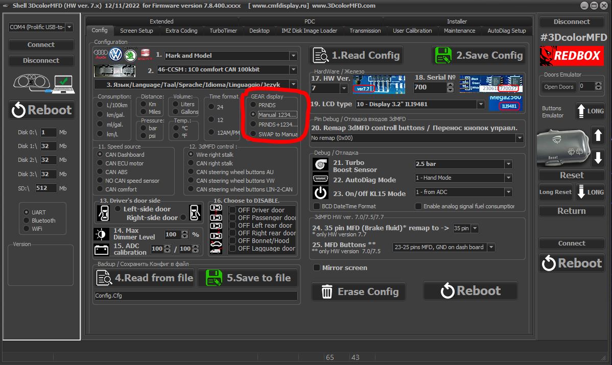
|
|
If the settings in the Configure tab are correct, but the N signal
does not appear when the clutch pedal is depressed. Check if the clutch pedal micro switch is present and working.
|
|
Если настройкf во вкладке Конфиг правильная, но при нажатии на
педаль сцепления не появляется сигнал N. Проверте наличие и работоспособность микровыключателся педали сцепления.
|
|
The signal from the bonnet contact sensor begins to be analysed when
the oil level warning signal is activated. If the bonnet is opened
after the oil level warning signal is activated, the control unit
will decide that oil has been added and will turn off the oil level
warning signal. However, if no oil has been added, the control
module will determine that the oil level is low after approximately
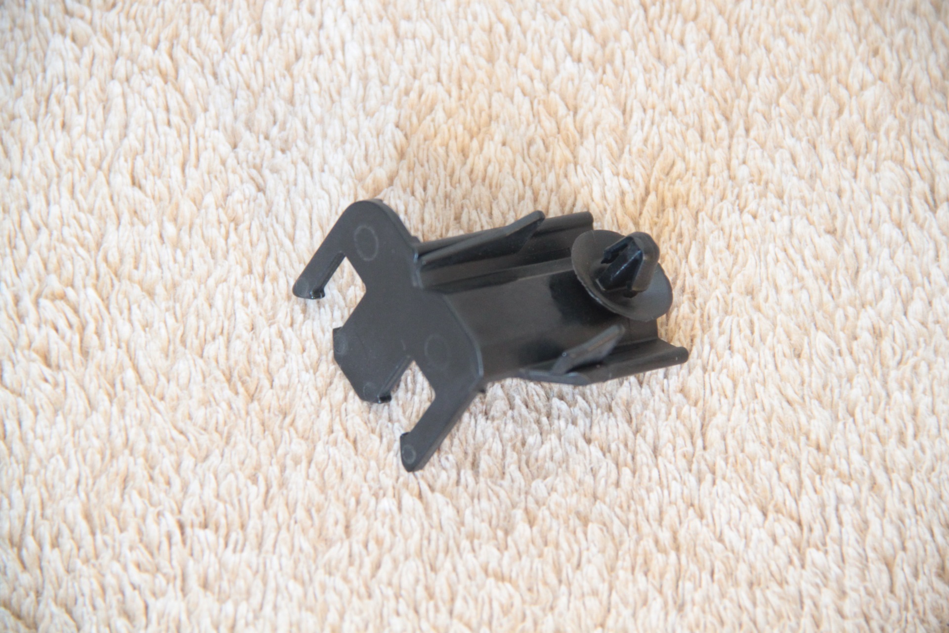
100 km of driving and will reactivate the low oil level signal. List of necessary spare parts: 1J0 953 236 B — F120 bonnet lock microswitch with wires 3B0 953 248 — bonnet position sensor mounting bracket 1J0 971 845 K — bracket (Thanks to MAXA20014 for the number) 1J0 973 722 — connector 000 979 133 — wire with terminals 357 972 741 — plug (2 pcs.)
|
|
Сигнал от контактного датчика капота начинает анализироваться при
включении предупредительного сигнала уровня масла. Если после
включения предупредительного сигнала уровня масла открыть капот, то
блок управления решит, что масло было долито, и выключит
предупредительный сигнал уровня масла. Однако если масло долито не
было, то модуль управления в течение приблизительно 100 км пробега
определит, что уровень масла низкий и вновь включит сигнал низкого
уровня масла. Список необходимых запчастей: 1J0 953 236 B — микровыключатель замка капота F120 с проводами 3B0 953 248 — скоба крепления датчика положения капота 1J0 971 845 K — кронштейн (Спасибо MAXA20014 за номер) 1J0 973 722 — разъем 000 979 133 — провод с клемами 357 972 741 — заглушка (2шт.)
|
|
|
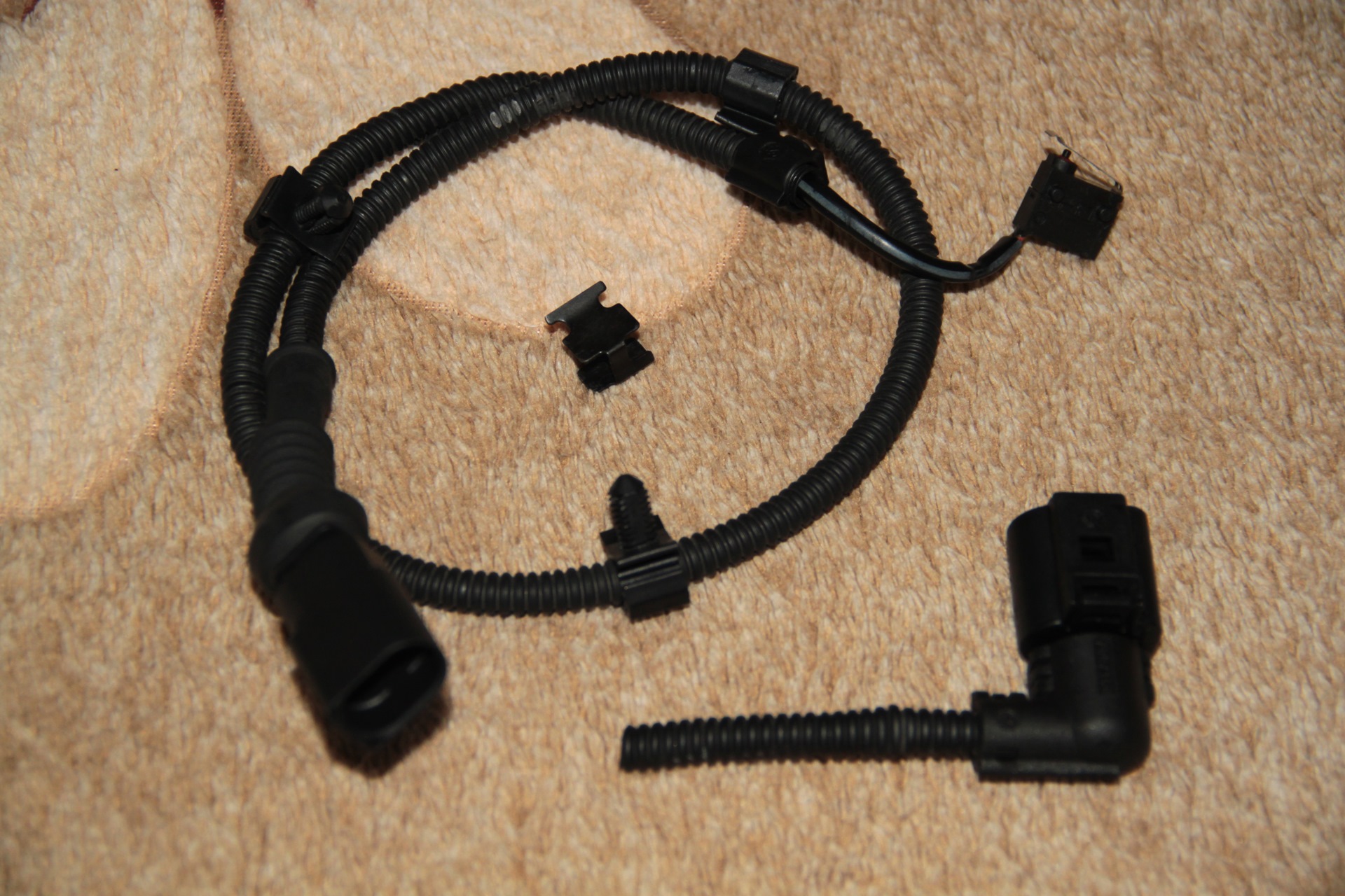
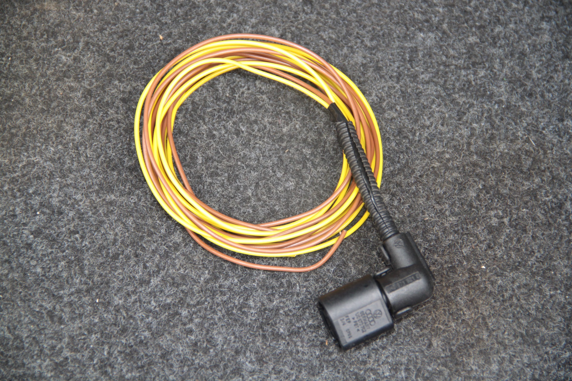
|
|
|
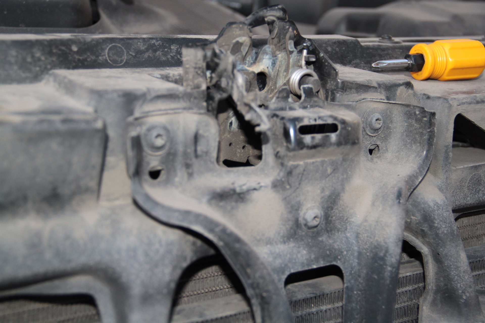
Installation is very simple. The lock, which was not originally
equipped with this microchip at the factory, still has a place for
its installation. I put the microchip in place and pressed it down
with a mounting bracket. To do this, I had to remove the radiator
grille, then I marked the position of the lock so that I could
install it as it was and not struggle with adjustments. I unscrewed
three Torx screws, removed the lock drive cable from the back,
pulled the amplifier slightly towards me, and removed the lock from
its place. |
|
Установка очень простая. Замок изначально не оборудованный с
завода этим микриком всё же имеет место под его установку. Поставил
микрик по месту и прижал его скобой крепления. Для этого
понадобилось снять решетку радиатора, далее я пометил положение
замка, чтобы установить как было и не мучится с регулировками.
Открутил 3 торкса, снял с обратной стороны тросик привода замка и
немного потянув на себя усилитель извлёк замок с его места. |
|
|
|
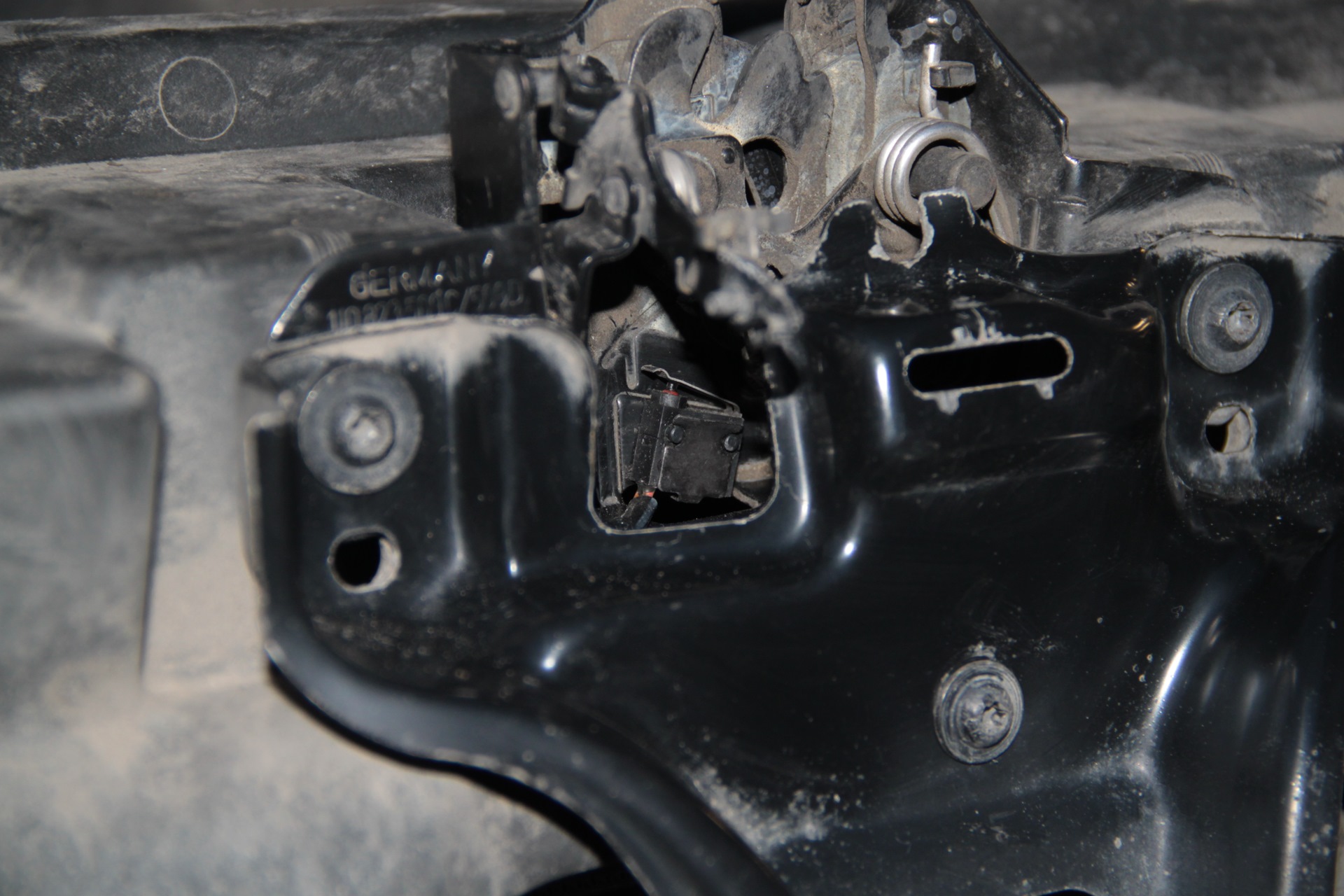
Lock with microswitch. The main thing is to position it correctly,
as shown in the photo, and secure it with a bracket.
|
|
|
|
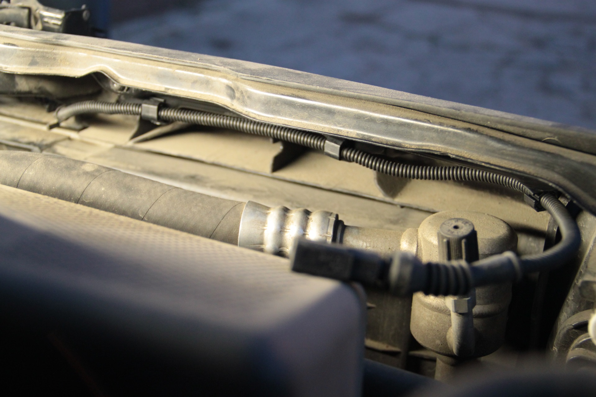
Next, reassemble in reverse order. Insert the wiring clips into the holes on the body part. Далее сборка в обратной последовательности. Вставил клипсы крепления проводки в отверстия на кузовной детали
|
|
|
|
Mounted on a bracket Крепится на кронштейне
|
|
|
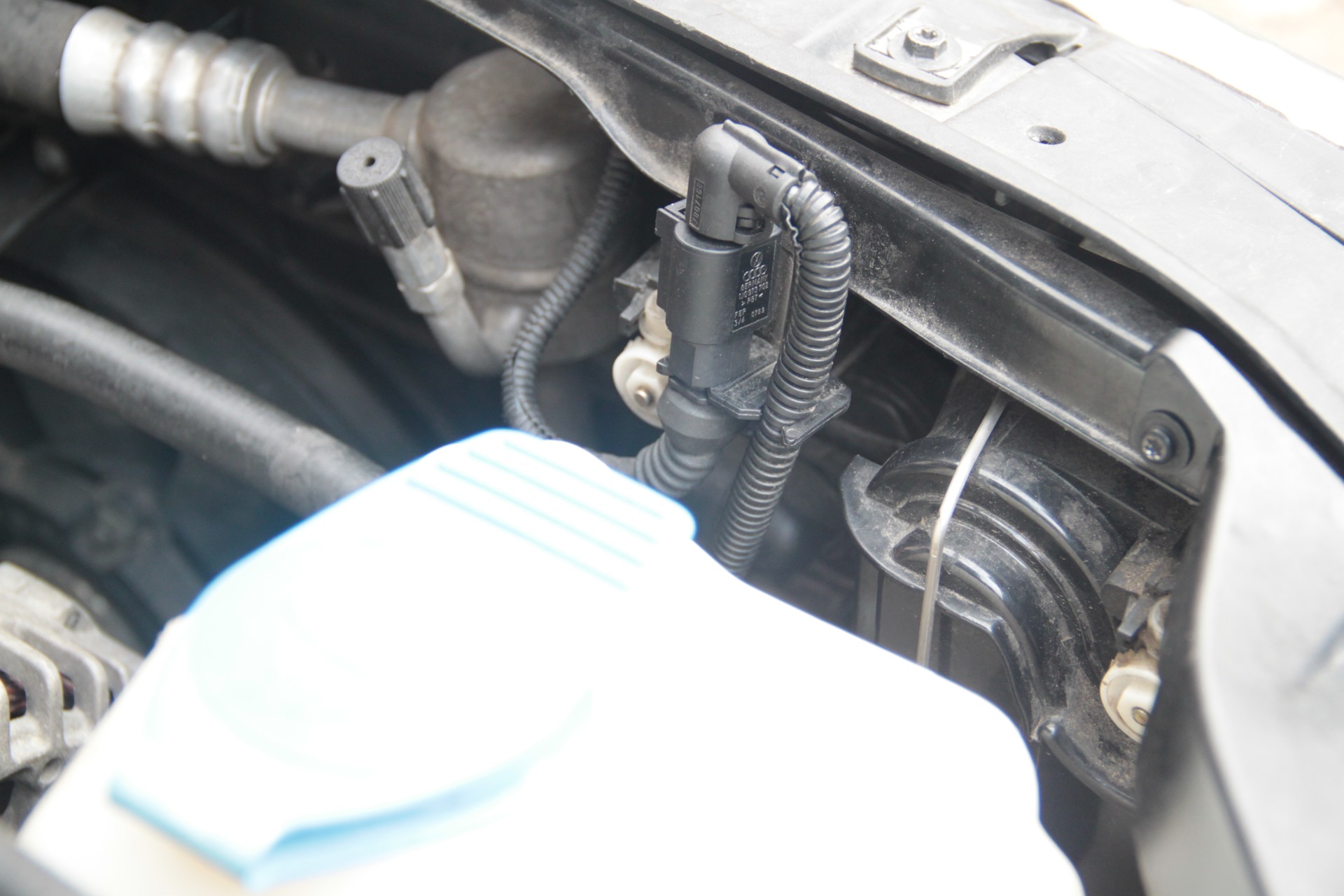
|
Its wires go to the left side of the engine compartment. One (brown)
wire goes to ground under the bonnet. The second (red-brown) wire is
connected to pin 22 of the green connector on the dashboard and to
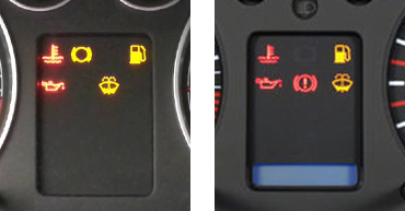
pin T15/1 of the 1J0 comfort unit connector. (For 1C0 — T15/5). After assembly, I immediately checked the functionality, got into the car and set the alarm, then pulled the bonnet release handle and immediately heard the siren working — it works! If you have a VDO instrument cluster, immobiliser 3. You can activate the bonnet open indicator. You need to solder a red LED, a 1kOhm resistor in a 1206 case and a BAS16 diode in an SOT23 case to it. I soldered the red LED into place. Его провода идут к левой части моторного отсека. Один (коричневый) провод идёт на массу под капотом. А второй (красно-коричневый) провод подключил к контакту 22 зеленому разъёму приборки и к контакту Т15/1 разъёма блока комфорта 1J0. (Для 1C0 — Т15/5). После сборки сразу же проверил работоспособность, сел в машину и поставил сигнализацию на охрану, за тем дёрнул ручку открывания капота, сразу же услышал работу сирены — работает! Если у Вас приборка VDO, иммо 3. Можно активировать индикатор открытого капота На ней нужно допаять светодиод красного цвета, резистор 1кОм в корпусе 1206 и диод BAS16 в корпусе SOT23. Припаял на своё место светодиод красного цвета.
|
|
|
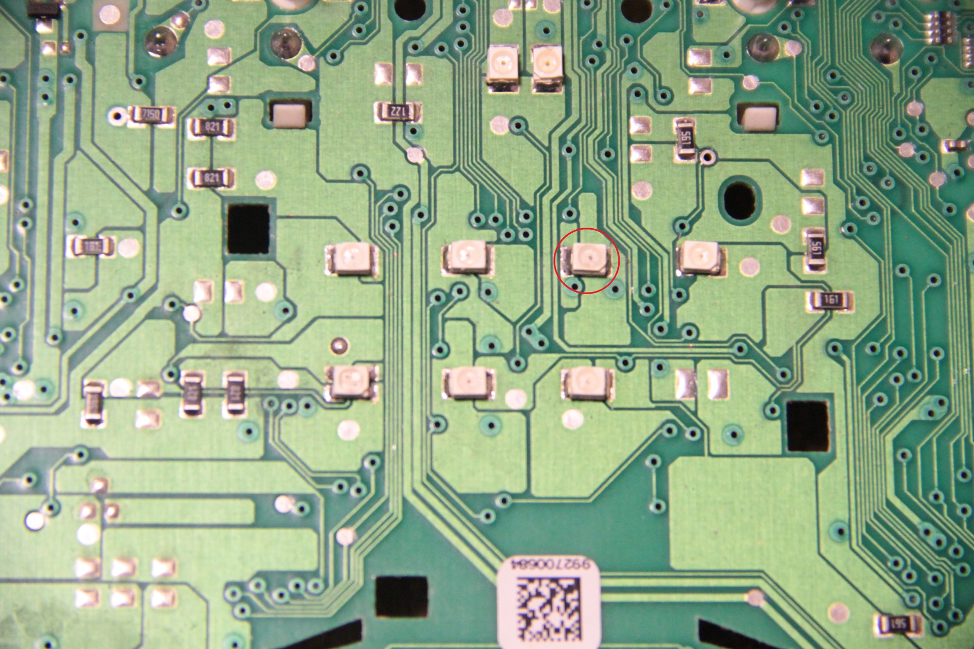
|
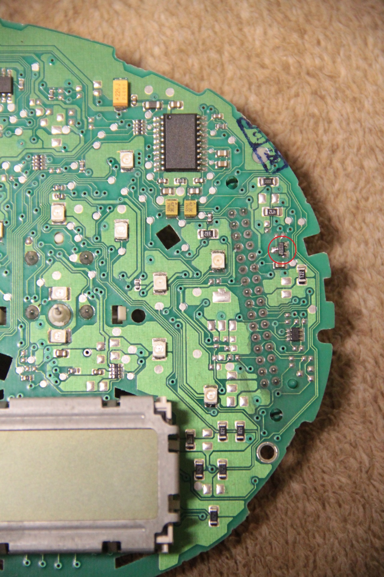
Near the green connector at input 22, I soldered a BAS16 diode in an
SOT23 package — the cathode is also at the input. Возле зеленого разъема на входе 22 припаял диод BAS16 в корпусе SOT23 — катод также на входе. |
|
|
|
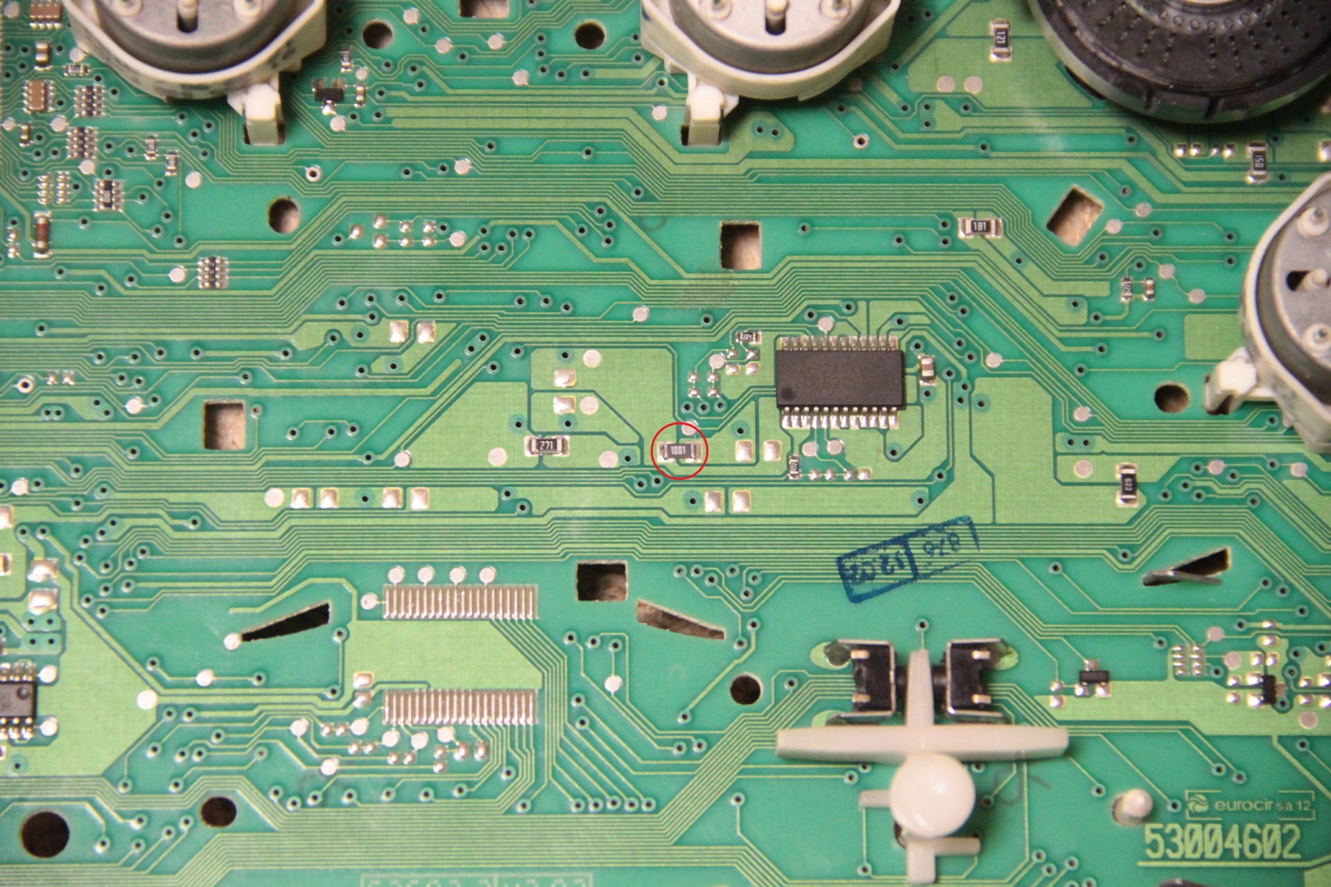
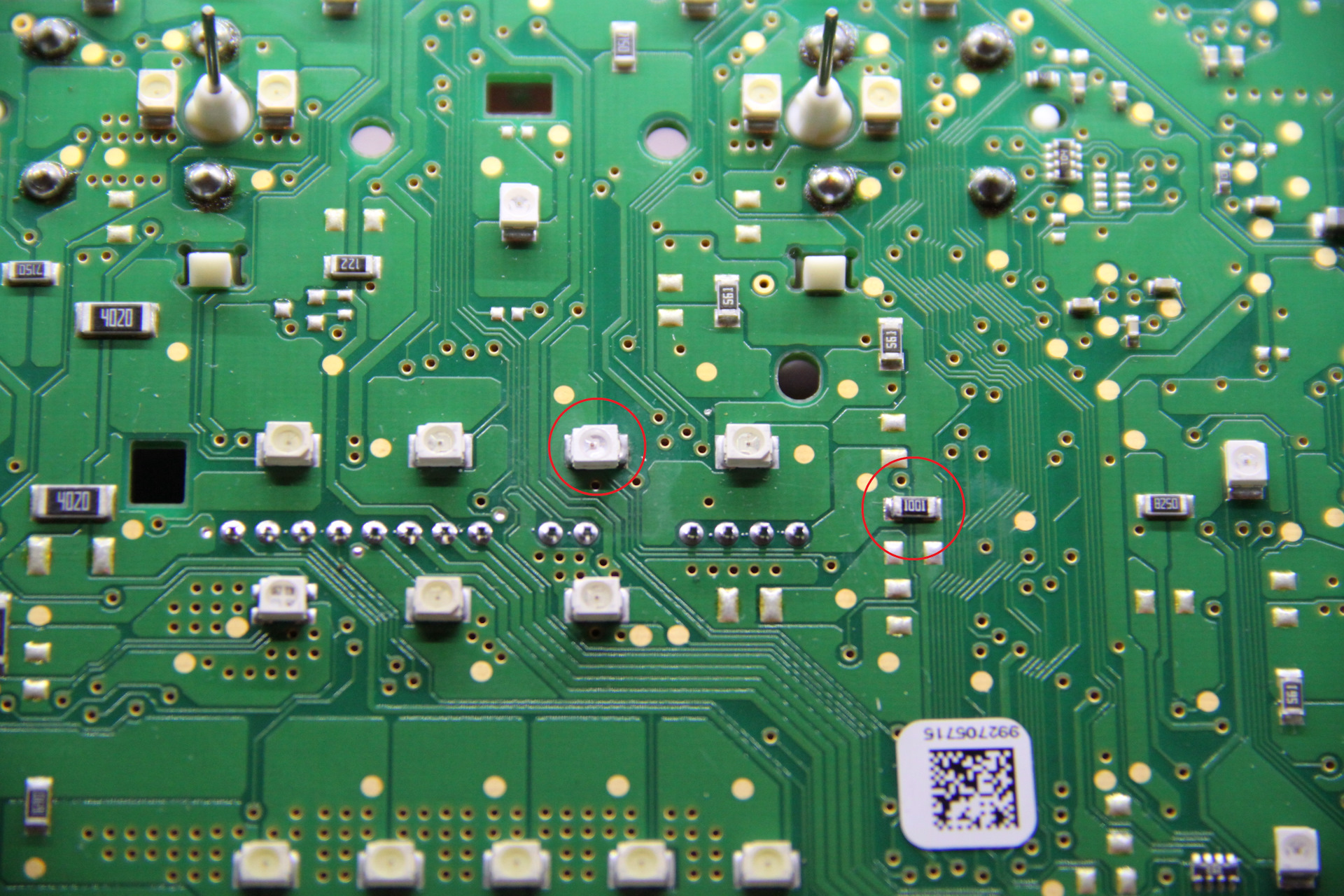
Well, on the other side, I closed the circuit with a 1 kOhm
resistor. Ну и с обратной стороны замкнул цепь резистором номиналом в 1кОм.
|
|
|
|
If you have a device with a half screen: Если у Вас приборка с половинчатым экраном:
|
|
|
|
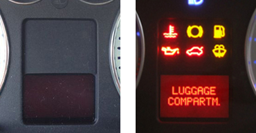
When the bonnet is opened, the indicator light
comes on. |
|
автор статьи про микровыключатель капота
|